2-8 Output Power Leveling Commands
Programming with GPIB Commands
2-20
PN: 10370-10374 Rev. F
MG369xC GPIB PM
2-8
Output Power Leveling Commands
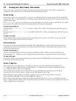
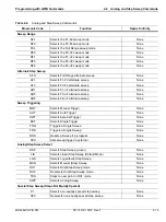
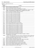
lists the output power leveling command mnemonic codes. These commands provide for
(1) selecting linear or logarithmic power level operation, (2) selecting an RF output power level, (3) leveling the
output power, and (4) turning the output power leveling off. In addition, commands are provided for the level
offset, power level sweep, ALC power slope, and step attenuator decoupling functions.
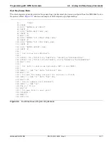
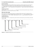
shows an example of an output power level command string.
Linear or Logarithmic Power Level Selection
Power level operations can be linear or logarithmic. The commands
LOG
,
PU0
, and
PU2
select logarithmic power
level operation. In logarithmic mode, power level entries and outputs are in dBm and power level sweeps are
logarithmic. This is the default mode.
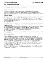
The commands
LIN
and
PU1
select linear power level operation. In linear mode, power level entries and
outputs are in mV and power level sweeps are linear.
RF Output Power Level Selection
The commands,
L0
thru
L9
, call up each of the preset (or previously set) output power levels. Each command
causes its associated RF power level to be output and opens that power level's parameter for data entry. Each
command will also deselect any other previously programmed power level and will turn off a power level
sweep, if active.
Alternate Sweep RF Output Power Level Selection
In the alternate sweep mode, the commands,
AL0
thru
AL9
, call up each of the preset (or previously set)
L0 to L9 output power levels. Each command causes its associated RF power level to be output during the
alternate sweep. Each command will also deselect any other previously programmed alternate sweep power
level. The commands do
not
open the L1 to L9 power level parameters for data entry. Use the commands,
XL0
thru
XL9
or
L0
thru
L9
, to enter new power level values.
Output Power Leveling
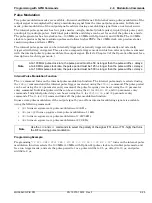
There are three output power leveling modes of operation—internal, external (detector or power meter),
and fixed gain (leveling off). The
IL1
command selects the internal leveling mode. In this mode, a signal from
an internal level detector is used to level the output power. This is the default mode.
The
DL1
command selects the external (detector) leveling mode; the
PL1
command selects the external
(power meter) leveling mode. In this mode, the output power is leveled using a signal from an external detector
(power meter) connected to the
EXTERNAL ALC IN
connector. In the external power leveling mode, the
EGI
command provides for entering a setting for the Reference Level DAC to control the ALC gain. The
LVO
command selects the fixed gain (leveling off) mode. Each command will also deselect any other previously
programmed output power leveling mode.
Programming Example:
Programming “
PL1 EGI 140 SPS
” selects external leveling of the output power using a signal from an
external power meter and sets the Reference Level DAC to 140.
Summary of Contents for MG369 C Series
Page 2: ......
Page 6: ...Contents 4 PN 10370 10374 Rev F MG369xC GPIB PM ...
Page 262: ...A 34 PN 10370 10374 Rev F MG369xC GPIB PM ...
Page 264: ...Index 2 PN 10370 10374 Rev F MG369xC GPIB PM ...
Page 265: ......


