Programmer’s Model
3-10
Copyright © 2002, 2003 ARM Limited. All rights reserved.
ARM DDI 0275D
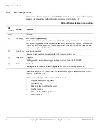
3.2.9
Control Register, r8
The Control Register is used to enable/disable the trace capture using bit 0. The Control
Register bit allocations are listed in Table 3-10.
Control register bit 0 drives the
TraceCaptEn
signal.
When
TraceCaptEn
is set the ETB11 SRAM is in write mode. If you attempt to read
the RAM Data Register read while
TraceCaptEn
is set, then the contents of the SRAM
are altered, resulting in the corruption of any stored trace data.
The ETB11 starts up from reset with the SoftwareCntl bit enabled. The value of this bit
can only be changed through the TAP controller. It is cleared when the
INTEST
instruction is selected by the TAP controller and is set by writing a 1 as normal. While
this bit is clear, all accesses to the register by the AHB interface are ignored.
Table 3-10 Control Register bit allocations
Bit
number
Name
Type
Function
[31:3]
-
-
Reserved
[2]
SoftwareCntl
Read/write (JTAG only)
Controls software and hardware register access:
1 = Software register access
0 = JTAG register access
[1]
Demux
Read/write
Demultiplexed memory support:
1 = Demultiplexed support enabled
0 = Demultiplexed support disabled
[0]
TraceCaptEn
Read/write
Trace capture enable:
1 = Trace capture is enabled
0 = Trace capture is disabled
Summary of Contents for ETB11
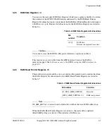
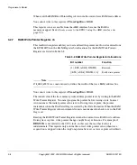
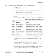
Page 6: ...List of Tables vi Copyright 2002 2003 ARM Limited All rights reserved ARM DDI 0275D ...
Page 8: ...List of Figures viii Copyright 2002 2003 ARM Limited All rights reserved ARM DDI 0275D ...
Page 46: ...Functional Description 2 26 Copyright 2002 2003 ARM Limited All rights reserved ARM DDI 0275D ...
Page 70: ...Signal Descriptions A 6 Copyright 2002 2003 ARM Limited All rights reserved ARM DDI 0275D ...
Page 78: ...Glossary Glossary 4 Copyright 2002 2003 ARM Limited All rights reserved ARM DDI 0275D ...


