Atmel AVR2052
45
8200M-AVR-11/11
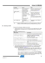
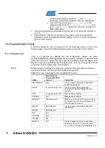
Option
Deafult value in
ATxmega256A3/D3
devices
Comments
BODLVL
1.6V
Resulting bytes:
FUSEBYTE0
0xFF
FUSEBYTE1
0x00
FUSEBYTE2
0xFF
FUSEBYTE4
0xFE
FUSEBYTE5
0xFF
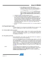
By default, programming with Serial Bootloader is not allowed, and so firmware can
be uploaded only over the JTAG interface. To turn on bootloader support, the
BOOTRST
fuse must be set to
BOOTLDR
which results in the following fuse bytes:
0xFF, 0x00, 0xBF, 0xFE, 0xFF
Second, a firmware image of the embedded bootloader (without OTAU support) shall
be programmed to the Atmel ATxmega256A3/Atmel ATxmega256D3
using JTAG.
After that, application images can be loaded to the device using the Bootloader PC
tool from the Serial Bootloader package, as described in Section
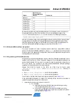
11.2.2 Extended (MAC) address assignment
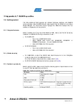
For proper operation all nodes in ZigBee network shall have unique MAC address
values. On the Atmel XMEGA platform, a unique
CS_UID
parameter must be specified
for each node in the application configuration, and then the application image must be
built separately for each board.
11.2.3 Programming with Serial Bootloader
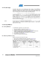
Programming using Serial Bootloader requires that the embedded bootloader code is
loaded to the device via JTAG. Firmware images for the embedded bootloader as
well as the Bootloader PC tool, which is needed to load the application image from a
PC to the device, are included in the Atmel Serial Bootloader software package
available for downloading from the Atmel website.
Images that shall be loaded to the MCU via JTAG may be found under
\Embedded_Bootloader_images\
in the
Atxmega256a3
/
Atxmega256d3
directory in
the package:
•
The
Bootloader_ATXmega256A3.hex
file for ATxmega256A3
•
The
Bootloader_ATXmega256D3.hex
file for ATxmega256D3
In both cases, the fuse bits should be configured properly (see
).
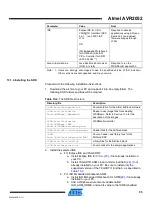
If the embedded bootloader is loaded, the following steps should be executed to
upload the application image file to the board:
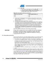
1. Assemble the board and connect it to the PC:
a. For STK600:
a. Assemble the Atmel STK600 board and ATxmega routing
b. Connect PC COM1 port to the RS-232 SPARE port of the
board. RS-232 SPARE pins should be connected to the MCU

