X20 system modules • Motor controllers • X20SM1436
X20 system User's Manual 3.10
2055
Mode 1 - Position mode
The position setpoint is specified in the Set position/speed register. The motor is then moved to this new position.
This is done with a ramp function that accounts for the defined maximum speed and acceleration values.
The position setpoint can also be changed during an active positioning procedure.
The position setpoint is specified in microsteps (1/256 of a full step).
If bit 0 in the General configuration register is 0 (no extended control word), then the position setpoint will be applied
as soon as it is different from the current position. The new position is then moved to.
However, if bit 0 in the General configuration register is set to 1 (extended control word), then the position setpoint
will be applied as described under "Mode 1 - Position mode with extended control word".
Mode 1 - Position mode with extended control word
The position mode with extended control word behaves like the previously described Position mode 1 (without
extended control word) except that the new position setpoint (Position/speed register) is applied according to the
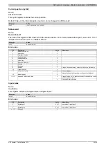
Extended control word
This register can be used to issue commands based on the module's state (see 4.25.7.15.7 "Ramp function model
Data type
Value
UINT
See bit structure.
Bit structure:
Bit
Description
Value
Information
0 - 3
Corresponds to the defaultControl word
x
0
Do not apply position setpoint
4
New setpoint
1
Apply position setpoint
0
Complete current positioning movement and then start next po-
sitioning movement
5
Change set immediately
1
Interrupt current positioning movement and then start next posi-
tioning movement
0
Position setpoint is an absolute value
6
abs / rel
1
Position setpoint is a relative value
7
Corresponds to the defaultControl word
x
0
Execute positioning
8
Halt
1)
1
Stop axis with deceleration
9 - 15
Corresponds to the defaultControl word
x
1)
This bit applies to all modes.
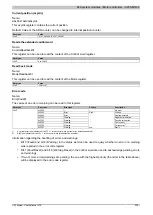
Extended status word
The bits in the status word reflect the status of the state machine (for a detailed description, see 4.25.7.15.7.2
"Status word" and 4.25.7.15.7.3 "State machine").
Data type
Value
UINT
See bit structure.
Bit structure:
Bit
Description
Value
Information
0 - 9
Corresponds to the defaultStatus word
x
If Halt = 0
0
Position setpoint not reached
1
Position setpoint reached
If Halt = 1
0
Axis decelerating
10
Target reached, depending on bit 8 (Halt) in the register Con-
1
Axis speed = 0
11
Corresponds to the defaultStatus word
x
0
Ramp generator did not apply the position value
12
Setpoint acknowledge
1
Ramp generator applied the position value
13 - 15
Corresponds to the defaultStatus word
x
Summary of Contents for X20 System
Page 2: ......


