4Timer
15
Copyright © 2018, www.
bluetrum.com. All Rights Reserved
15
4
Timer
4.1
Features
1.
Timer0/1/2, only support 32bit timer function
2.
Timer3/4/5, can be configured to Timer-mode, Counter-mode, Capture-mode and PWM-mode
4.2
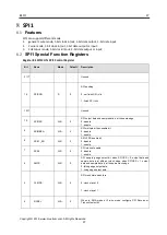
Timer0/1/2 Special Function Registers
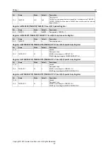
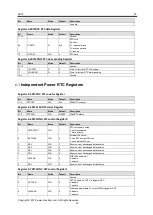
Register 4-1TMR0CON/TMR1CON/TMR2CON: Timer0/1/2 Control Register
Bit
Name
Mode
Default
Description
31:10
-
-
-
Unused
9
TPND
WR
0
Timer overflow pending
0: not overflow
1: overflow
8
-
-
-
Unused
7
TIE
WR
0
Timer overflow interrupt enable
0: disable
1: enable
6
INCSRC
WR
0
Increase source select
0: select TMR_INC
1: select external PIN
5:4
-
-
-
Unused
3:2
INCSEL
WR
0x0
Increase clock selection
00: System Clock
01: Counter input rising
10: Counter input falling
11: Counter input edge
1
-
-
-
Unused
0
TMREN
WR
0
Timer Enable Bit
0: Disable
1: Enable
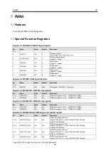
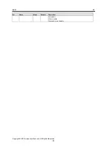
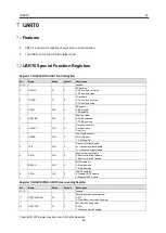
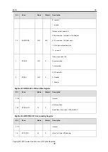
Register 4-2TMR0CPND/TMR1CPND/TMR2CPND: Timer0/1/2 clear pending Register
Bit
Name
Mode
Default
Description
31:16
-
-
-
Unused
9
TPCLR
W
0
Timer overflow pending clear bit
0: inactive
1: clear pending
8:0
-
-
-
Unused
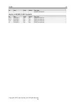
Register 4-3TMR0CNT/TMR1CNT/TMR2CNT: Timer0/1/2 counter Register
Bit
Name
Mode
Default
Description
31:0
TMRCNT
WR
0x0
Timer counter.
TMRCNT will increase when timer is enabled. It overflows when TMRCNT =
TMRPR, TMRCNT will be clear to 0x0000 when overflow, and the interrupt
flag will be set ‘1’.
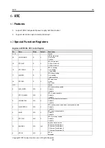
Register 4-4TMR0PR/TMR1PR/TMR2PR: Timer0/1/2 period Register
Bit
Name
Mode
Default
Description
31:0
TMRPR
WR
0xffffffff
Timer period = TMRPR + 1

