background image

6

Here are some of the possibilities:
-  expansion of number of entry panels 
and internal extension per block;
- customization of system activation 
time and duration of call;
-  programming  of  all  internal  exten-
sions by software. In this case it is nec-
essary to collect the ID codes and to 
insert them in the tables attached to the 
programming devices;
-  customization  of  identifying  texts  for 
user positions and entry panels.

CONFIGURATION OF THE SYSTEM 
WITH PROGRAMMING IN BASIC 
MODE AND DEFAULT SETTINGS

Maximum limits of the system

-  Maximum number of XA/301LR: 1.
-  Maximum  number  of  blocks  X2-X1: 

64. 

-  Maximum number of entry panels per 

block X2-X1: 4.

-  Maximum  number  of  entry  panels 

300: 20 (19 with IPD/300LR).

-  Maximum  number  of    porter  switch-

boards IPD/300LR: 1.

-  Maximum number of users connected 

directly to XA/301LR: 100 (0 if present 
blocks X2-X1).

-  Maximum  number  of  users  on  block 

X2-X1:  100  (99  with  porter  switch-
board IPD/300LR with encoded entry 
panel HAC/300).

-  Maximum  number  of  relay  actuators 

IOD/303LR: 1.

Default settings
•  System activation time:


  call 30 s, conversation 60 s maximum.
•  Door-lock release activation time: 
-  for entry panel 300 (with ICP/LR) with 

selectable buttons from 1 s, 4 s, 8 s 
and 16 s;

-  for entry panel HAC/300LR adjustable 

from 1 s to 255 s;

-  for entry panel X2-X1 adjustable from 

1 s to 15 s;

•  Aux  1  command  and  door  lock 

release active only when internal 
extension is called.

•  Self-connection  and  scanning  only 

on block entry panels X2-X1. 

•  Automatic  assignment  of  first  key 

of all entry panels 300 and X2-X1 as 
porter call.

m

 ATTENTION

The SERVICE button for program-
ming the unit is located near the 
terminals. Be especially careful with 
the terminals (~ ~) shown in figure 1 
by the letter A, as voltage is present.

Basic programming

Programming structures the system 
through the assignment of an  identi-
fication code unique to all LON devices 
(e.g. ICP/LR, HAC/300LR, IPD/300LR) and 
X2-X1 (e.g. internal extensions and block 
entry panels X2-X1 such as HEV/301, 
HEC/301, etc.).
Programming is divided into two parts:
- programming of entry panels and 

accessories.

-  programming of internal extensions.

Accessing and exiting basic pro-
gramming

To access programming, you must press 
the SERVICE button. 
Programming is accessed by the 
sequence described below.

Access to programming of entry panels.

The yellow LED is off
1 -  Press the SERVICE button for at least 

3 s, 

the yellow LED flashes steadily.


2 - Press the SERVICE button again for 

at least 3 s,

 the yellow LED stays on.


3 -  To exit programming, press the serv-

ice button for about 1 s, 

the yellow 

LED goes off.


Access to programming of internal 
extensions.

The yellow LED is off
1 -  Press the SERVICE button for at least 

3 s, 

the yellow LED flashes at a steady 

rate.


2 -  To exit programming, press the serv-

ice button for about 1 s, 

the yellow 

LED goes off.

NOTE:

When you exit programming mode by 
pressing the SERVICE button for 1 s, this 
starts automatic programming of any 
IPD/300LR and IOD/300LR.

PROGRAMMING

Power up the XA/301LR power supplier 
and proceed as follows. 

1 -  PROGRAMMING OF ENTRY 

PANELS 300, BLOCK ENTRY 
PANELS X2-X1 MASTER 

Programming, in addition to establish-
ing the order of scanning of the entry 
panels, allows you to set the type of 
entry panel 300 (audio or video entry 
control), the duration of the command 
for opening of the solenoid lock (only 
for 300 plates with buttons) and the 
definition of the number of X2-X1 but-
tons in the system.

1.1 - 

Access 

programming of entry 

panels 

(yellow LED on).

300 entry panels 
(ICP/LR or HAC/300LR)
 (fig. 7)

In entry panels with button (ICP/LR) the 
busy signal light comes on (if present), 
while in digital entry panels (HAC/300LR) 
the message CONFIGURATION MODE 
appears.

1.2 - 

Programming of 

entry panel

 and 

door lock release time.

•  Programming  of  video entry panel 

ICP/LR and door lock release time1 s.

-  Press call button no. 1.

Wait for two acoustic confirmation notes.

•  Programming  of  audio entry panel 

ICP/LR and door lock release time1 s.

-  Press call button no. 1.

Wait for two acoustic confirmation notes.

-  Again press call button no. 1.

Wait for an acoustic confirmation note.


•  Programming of video entry panel 

HAC/300LR and door lock release 
time1 s.

-  Type in the first code followed by  .

Wait for two acoustic confirmation notes.

•  Programming of audio entry panel 

HAC/300LR and door lock release 
time1 s.

-  Type in the first code followed by  .

Wait for two acoustic confirmation notes.

-  Again type in the first code followed by  .

Wait for an acoustic confirmation note.


1.3 - 

Repeat the procedure from point 

1.2  on  the  next  entry  panels  (in  the 
desired order of scanning of the entry 
panels).

When the procedure is complete, the busy  
light goes off or the CONFIGURATION 
MODE message disappears to indicate 
that programming is complete.


NOTE.

•  If  you  want  to  modify  the  activation 

time of the door lock release in IPC/LR 
from 1 s to 4 s, 8 s or 16 s, perform the 
steps in point1.2 or 1.3 using respectively 
call button no. 2, 3, 4.

•  On  HAC/300LR  plates,  the  time  can  be 

programmed directly from the entry 
panel referring to the manual.

Block entry panels X2-X1 Master 
(HEV/301, HEC/301, AZV/304, etc.) 
(fig. 7)

ATTENTION. Programming of block entry 
panels X2-X1 will be possible only with 
units that are version 3.0 or later.

1.4 - 

For the definition of each block 

entry panel X2-X1 Master, the two 
sequential steps listed below are 
required.

A -  Identification 
block entry panel

•   Remove  and  re-connect  jumper 

SW2 of the 

first entry panel 

(Master) 

connected to the power supplier 
XA/301LR, (fig. 7) of 

the first block 

X2-X1

 and wait for confirmation.

Confirmation is signalled by a double 
acoustic signal with activation of the sole-
noid lock command.

B -  Definition of number of calls
users of the block

This programming is to be carried out 
only from the Master entry panel as 
follows: 

•  Definition of the number of buttons 

used in the audio/video entry panel 
(0, 1, 2, 3 or 4):

- press the last button used on the 

audio/video entry panel (fig. 8-A);

- press button 1 (brown, black wiring) 

if you intend to use a call button. 
Press button 2 (red, black wiring) if 
you intend to use two call buttons. 
Proceed in the same way to define the 
other call buttons.

-  If no call buttons are connected, press 

the first button of the additional entry 
panel (fig. 8-B).

•  Definition  of  total  number  of  users 

connected on block X1, X2:

- Press the first button used on the 

audio/video entry panel (IF USED), or 
the first button on the additional entry 
panel HEP/306 and the last button 
used on the audio/video entry panel 
(or additional panel).

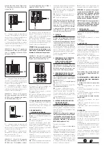
A

B

1-M

2-R

3-C
4-G

1-M
2-R
3-C
4-G

N

8

1.5 - 

Repeat the procedure in point 2.4 

for the subsequent 

Master entry panels


of the other blocks. 
Programming of 

Slave entry panels

 of 

the same block (fig. 7) must be done 
afterwards (see paragraph 

“Program-

ming  X2-X1 Slave entry panels”

).

1.6 - 

Exit programming.

Examples of definition 
number of user calls

EXAMPLE 1 - Block X2-X1 with Targha 
audio entry panel with 3 calls, without 
additional button panels (fig. 9).

1A

9

1 - 

Press call button no. 3 (position 

1A) to define the number of buttons 
used (3) in the audio/video panel.

Wait for the confirmation note (*).

2 - 

Press the same button again to 

define the total number of user calls for 
the block (3).

Wait for the confirmation note (*).

EXAMPLE 2 - Block X2-X1 with Targha 
audio entry panel with 10 calls and 
additional button panels (fig. 10).

1B

2B

10

1 - 

Press call button no. 4 (position 1B) 

to define the number of buttons used 
(4) in the audio/video panel.

Wait for the confirmation note (*).

2 - 

Then press call button no. 10 (posi-

tion 2B) to define the total number of 
user calls for the block (10).

Wait for the confirmation note (*).

EXAMPLE 3 - Block X2-X1 with Targha 
video entry panel with 12 calls and 
additional button panels (fig. 11).

2C

1C

11

1 - 

Press call button no. 1 (position 

1C) to define the number of buttons 
used (0) in the audio/video panel.

Wait for the confirmation note (*).

Summary of Contents for XA/301LR

Page 1: ...totest attiva LED acceso programmazione posti esterni attiva o malfunzionante LED spento funzionamento normale LED lampeggia velocemente corto circuito su linea X2 o su linea LON Presa RJ45 fig 1 Questa presa permette il collegamen to al dispositivo di programmazione IPC 300LR o IPC 301LR Caratteristiche tecniche Alimentazione 230 V AC 50 60 Hz L apparecchio è protetto elettronica mente contro sov...

Page 2: ...nterni e posti esterni di blocco X2 X1 quali HEV 301 HEC 301 ecc La programmazione è suddivisa in due parti programmazione posti esterni ed accessori programmazione dei derivati interni Ingresso ed uscita dalle program mazioni base Per accedere alla programmazione è necessario premere il pulsante SERVICE L accesso alla programmazione avviene mediante la sequenza descritta di seguito Accesso alla p...

Page 3: ...tendere due note acustiche di conferma Programmazione posto esterno citofonico HAC 300LR e tempo apriporta 1 s Digitare il primo codice seguito da Attendere due note acustiche di conferma Digitare nuovamente il primo codice seguito da Attendere una nota acustica di conferma 1 3 Ripetere la procedura del punto 1 2 sui posti esterni successivi nell or dine desiderato di scansione dei posti esterni T...

Page 4: ...scita dalla program mazione l accensione del LED giallo per un 1 s circa indica che l operazione di programmazione automatica è stata completata L uscita dalla programmazione è confer mata dal LED spento 4 PROGRAMMAZIONE AUTOMATICA DI EVENTUALI IPD 300LR E IOD 303LR IN ASSENZA DI POSTI ESTERNI Negli impianti senza posti esterni 300 o X2 X1 la programmazione di un IPD 300LR richiede di effettuare u...

Page 5: ...ected against overloads and short circuits In addition the two power supplies 18V and 20V have galvanic insulation Electrical input 120 VA Dissipated power 22 W max and 8 W in stand by Power supply for entry panels and or internal extensions of video entry con trol X2 and accessories 18 V DC 2 A 2 5 A peak Power supply for entry panels and or internal extensions of video entry con trol X1 and acce...

Page 6: ...ress call button no 1 Wait for two acoustic confirmation notes Programming of audio entry panel ICP LR and door lock release time1 s Press call button no 1 Wait for two acoustic confirmation notes Again press call button no 1 Wait for an acoustic confirmation note Programming of video entry panel HAC 300LR and door lock release time1 s Type in the first code followed by Wait for two acoustic confi...

Page 7: ...rom which to programme the internal exten sions before activating programming of the internal extension ATTENTION Modification of the user programming device may be done only after programming the entry panels chapter 1 and or switch board IPD 300LR chapters 3 and 4 Proceed as follows 6 1 Activate programming of the internal extensions From the 300 entry panel that you plan to use for programming ...

Page 8: ...n ACHTUNG Das Netzgerät muss IMMER horizon tal installiert werden falls das Gerät in einem Gehäuse untergebracht ist für ausreichende Lüftung sorgen Das Gerät kann mit der beiliegenden DIN Schiene an der Wand installiert werden dabei die schützenden Klem menabdeckungen verwenden Abb 3 4 Das Gerät kann in einem eigenem Schaltkasten auf einer DIN Schiene EN 50022 Abb 5 installiert werden Für die Dem...

Page 9: ...rten Erneut den ersten Code gefolgt von eingeben Einen bestätigenden Ton abwarten 1 3 Den Vorgang unter Punkt 1 2 bei den nachfolgenden Außenstationen in der für die Abtastung der Außenstationen gewünschten Reihenfolge wiederholen Die Leuchtanzeige der besetzten Leitung oder die Meldung KONFIGURATIONSMO DUS schalten sich bei erfolgter Program mierung automatisch aus ANMERKUNG Falls man die Betätig...

Page 10: ...rlangt die Programmierung eines IPD 300LR einen Ein und Aus trittszyklus 5 PROGRAMMIERUNG SLAVE AUSSENSTATIONEN X2 X1 Dieser Vorgang muss nach der Program mierung der unter Punkt 1 beschriebe nen Geräte durchgeführt werden 5 1 Auf die Master Außenstation des Blockes gehen 5 2 Die Überbrückungsklemme SW1 der Master Außenstation entfernen 5 3 Die akustische Bestätigung abwar ten Die Anzahl der Hörtö...

Page 11: ...extérieurs de bloc Master et Slave HEV 301 HEC 301 HET 301 AZV 304 AZ 304 Bloc n 2 X2 X1 Bloc n 1 X2 X1 Centrale Postes extérieurs 300 INSTALLATION RÉSIDENTIELLE AVEC BLOCS X2 X1 Poste extérieur de bloc X2 X1 Postes extérieurs de bloc X2 X1 postes extérieurs active ou ne fonction nant pas bien LED éteinte fonctionnement normal LED clignote rapidement court cir cuit sur ligne X2 ou sur ligne LON Pr...

Page 12: ...installation 1 1 Entrer dans la programmation des postes extérieurs LED jaune allumée Postes extérieurs 300 ICP LR ou HAC 300LR fig 7 Sur les postes extérieurs à bouton ICP LR s allume le signal lumineux de ligne occu pée si présent tandis que sur les postes extérieurs numériques HAC 300LR appa raîtlemessageMODEDECONFIGURATION 1 2 Programmationduposteextérieur et du temps de l ouvre porte Programm...

Page 13: ...uelle centrale de conciergerie IPD 300LR ou d accessoires IOD 300LR présents sur l installation Après chaque sortie de la programma tion l allumage de la LED jaune pen dant environ 1 s indique que l opération de programmation automatique a été complétée La sortie de la programmation est confir mée par la LED éteinte 4 PROGRAMMATION AUTOMATIQUE D ÉVENTUELS IPD 300LR ET IOD 303LR EN L ABSENCE DE POS...

Page 14: ... dis positivo de programación IPC 300LR o IPC 301LR Características técnicas Alimentación 230 V ca 50 60 Hz El aparato está protegido electrónica mente contra sobrecargas y cortocircui tos además las dos alimentaciones 18 V y 20 V están aisladas por galvanizado Potencia absorbida 120 VA Potencia disipada 22 W máx y 8 W en estado de espera Alimentación placas externas y deriva dos internos de video...

Page 15: ... la programación de las placas externas LED amarillo encendido Placas externas 300 ICP LR o HAC 300LR fig 7 En las placas externas con botón ICP LR se enciende el señalador luminoso de línea ocupada si está presente mien tras que en las placas externas digita les HAC 300LR se muestra el mensaje MODO CONFIGURACIÓN 1 2 Programación placa externa y tiempo abre puerta Programación placa externa video ...

Page 16: ...s internos o placas externas prevé el reconocimiento automático de la centralita de portería IPD 300LR si estuviera presente o accesorios IOD 300LR presentes en la instalación Al final de cada salida de la programa ción el encendido del LED amarillo durante 1 s aproximadamente indica que la operación de programación automática ha sido completada La salida de la programación se confirma por medio d...

Page 17: ...aster 1 2 3 4 5 6 9 8 7 0 C T S P Placas botoneiras de bloco Master e Slave HEV 301 HEC 301 HET 301 AZV 304 AZ 304 Bloco n 2 X2 X1 Bloco n 1 X2 X1 Central Placas botoneiras 300 INSTALAÇÃO RESIDENCIAL COM BLOCOS X2 X1 Placa botoneira de bloco X2 X1 Placas botoneiras de bloco X2 X1 Saída alimentação placa botoneira 18 V DC A Saída áudio pela placa botoneira Régua de bornes C XUP Linha X1 vídeo porte...

Page 18: ...DE BLOCO X2 X1 MASTER A programação para além de estabe lecer a ordem de varredura das placas botoneiras permite a configuração do tipo de placa botoneira 300 porteiro ou vídeo porteiro a duração do comando de abertura da fechadura eléctrica esta última somente para placas com botões 300 e a definição do número de blocos X2 X1 da instalação 1 1 Entrar na programação das placas botoneiras LED amare...

Page 19: ...rios IOD 300LR presentes na instalação No final de cada saída da programação o acendimento do LED amarelo durante quase 1 s indica que a operação de pro gramação automática foi finalizada A saída da programação é confirmada pelo LED apagado 4 PROGRAMAÇÃO AUTOMÁTICA DE EVENTUAIS IPD 300LR E IOD 303LR NA AUSÊNCIA DE PLACAS BOTONEIRAS Nas instalações sem placas botoneiras 300 ou X2 X1 a programação d...

Page 20: ...amento Fig 15 Colour coding of wires relating to CN2 CN3 wiring for connecting interface HIA 300 to the units installed in front plates HPV 1 and HPC 1 WARNING Which wire is used for connec tion will depend on the number of buttons installed Abb 15 Farbe der Kabelleiter CN2 CN3 für den Anschluss zwischen der Schnittstelle HIA 300 und den Einheiten die in der Außenstation HPV 1 und HPC 1 einge baut...

Reviews: