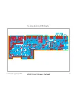
The Power Supply PCB
This carries:
Power supplies for everything except power amps
Mains on/off and inrush control switching relays
X2 capacitor
The mains-fail detect circuit
There are four power supply rails:
+15V Opamp supply
-15V
Opamp supply
+9V
Relay supply
+5V
Microcontroller, logic and comparator supply
The power supply board also carries the mains switching relays that control the supplies to the power
amplifiers. When the amplifier goes from standby to ON, the inrush control relay RL4 closes first with
R78 limiting the inrush current. After 3 seconds (while speaker-short testing is going on- see below) the
On/Off relay RL3 closes. 100 msec later (to ensure no break in the supply) RL4 opens. When the
amplifier goes from ON to standby, RL3 simply opens.
The front panel PCB
This carries:
The main PIC
The volume rotary encoder and control switches.
The LCD display
Shift registers for driving the relays
The RS232 interface for control and software updates
U1 is the main housekeeping microcontroller for the amplifier; it is a 16F977A PIC running at 20 MHz. It
handles all the control functions of the amplifier except for those on the A-BUS hub PCB, which are
dealt with by another PIC on that board.
PIC pins handling amplifier conditions:
Pin
Normal
Active
Speaker short-circuit detect
7
LOW
HIGH Active= short found
Phones detect
27
HIGH
LOW Active= Phone jack in
Mains fail 28
LOW HIGH
DC offset protection
29
HIGH
LOW
Overtemperature protection
30
HIGH
LOW
Overload protection
33
HIGH
LOW
Clip detection
34
HIGH LOW
The LCD display module interfaces to the front panel PCB through CN2. Display data from the PIC is
clocked serially into shift register U2 and sent to the LCD module in byte-wide parallel format. The
LCD module is powered from the +5V rail.
52


