APPENDIX B: Register listing for Vari Pro-option
Note! Observe proper delays when communicating over Modbus. Use at least 200
ms polling delay. If you observe bus errors, increase the delay until there are no
errors. Continuously rewrite ( = refresh) fan speed, cooling valve, and heating valve
registers at least every 5 minutes, even when desired value is 0. Always write to all
3 registers, even if there is no heating (or cooling) option in the unit.
When controlling fan coil directly (without the room controller), use the following
register map.
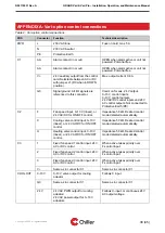
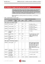
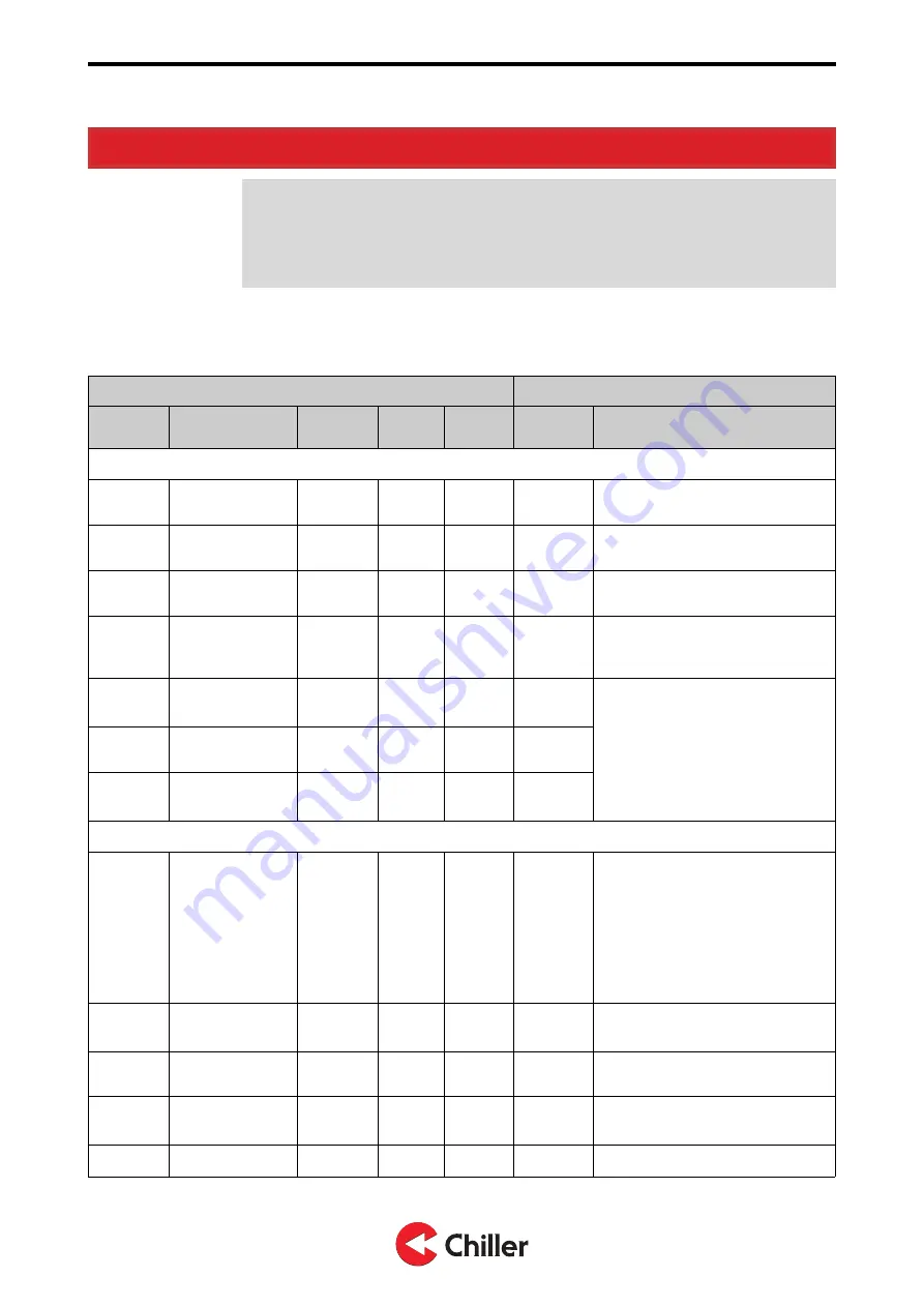
Table 3: Register listing for Vari Pro-option
Vari Pro FCU Controller Card Register Map v 1.4
Modbus RTU RS485 38400, 8N1
Description
Read/
Write
Min.
Max.
Unit
Note(s)
Write register 16 bit integer register
4x00002
Set fan speed
W
0
100
%
0...100 = 0...10 V
0 = OFF 100 = ON 24 V
4x00003
Set cool output
W
0
100
%
0...100 = 0...10 V
0 = OFF 100 = ON 24 V
4x00004
Set heat output
W
0
100
%
0...100 = 0...10 V
0 = OFF 100 = ON 24 V
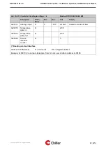
4x00101
Reset service
reminder
counter
W
0
1
1 = reset
4x35203
Manufacturing
year
W
20xx
20xx
By reading this data, modbus
register configuration and
address alignment can be
validated.
4x35204
Manufacturing
month
W
1
12
4x35205
Manufacturing
day
W
1
31
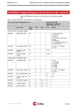
Read register 16 bit integer register (*)
3x00005
Alarm register
R
Bit0: Condense sensor alarm
Bit1: Missing RPM from fan1
Bit2: Missing RPM from fan2
Bit3: Sensor fault, water in
Bit4: Sensor fault, water out
Bit11: Parameter file
Bit15: Service reminder (Filter
alarm)
3x00007
Current fan
speed output
R
0
100
%
Scaled to maximum speed
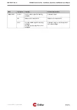
3x00010
Condensate
tank state
R
0
3
Level 2 pump start, 3 alarm
3x00011
Condensate
pump status
R
1
16
1 = OFF, 16 = ON
3x00012
Cooling output
R
0
1000
x10mV
Scaled to maximum flow
Copyright © 2020. All rights reserved.
40 (45)
N02119031 Rev. A
GRAND Vari & Vari Pro – Installation, Operation, and Maintenance Manual


