User Manual DEV 1953
Copyright DEV Systemtechnik GmbH 2015-2017
107
5.8
Control via Remote Interface: QEC Protocol
5.8.1
QEC Protocol Overview
The QEC protocol is another standard for the communication between a host and
the device and can be used for the monitoring and for the switching of the device.
As within the Sandar Prosan protocol messages between the device and the host
are transferred as records, i.e. data between unique header (
<STX>
,
<ACK>
or
<NAK>
)
and end (
<ETX>
) characters. Each record includes a header byte, a two-byte address,
then either a command byte and necessary data bytes or a negative response byte,
then an end byte, and a checksum byte.
This QEC protocol implementation covers a subset of commands of the protocol
version v2.15 and is implemented to work via TCP/IP on port 23 (standard Telnet
port), and/or via serial interface.
Note:
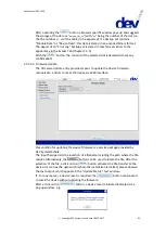
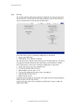
The QEC protocol is available only if "QEC" is selected within the CPH setup of
the Web Interface; please refer to chapter 5.5.7.2.3. If it is intended to use the
serial interface to control the device via QEC protocol, the settings of the serial
interface have to be configured accordingly (chapter 4.4.1.1).
If the serial interface is used for the communication, the QEC serial address
(see below) can be selected via the CPH setup of the Web Interface.
Within the QEC protocol, the DEV 1953 is treated as a 32x16 matrix. Naturally,
the input ports of a switch module cannot be routed to the output port of a
different switch module.
5.8.2
QEC Protocol Communication Structure
The basic command structure is:
Command:
<STX><address><command>{<data>}<ETX><checksum>
Positive Response:
<ACK><address><command>{<data>}<ETX><checksum>
Negative Response:
<NAK><address><negative_response><ETX><checksum>
Notation:
<STX>
= start character (=
0x02
) [command header]
<ETX>
= stop character (=
0x03
) [command/response end]
<ACK>
= acknowledge character (=
0x06
) [positive response header]
<NAK>
= not-acknowledge character (=
0x15
) [negative response header]
Note:
A command starts with an
<STX>
character; a positive response to a command
starts with an
<ACK>
character; and a negative response starts with the
<NAK>
character.
The
<address>
consists of two ASCII bytes representing the device address.
When using the serial interface for the communication, the hexadecimal QEC
serial address is used as the device address; please refer to chapter 4.3.7. If the
device is addressed via Ethernet, the device address is
0xFF
.
The
<command>
is one hexadecimal ASCII byte representing the command issued.
The
<data>
part is required for selected commands and in selected positive
responses only and consists of one or more hexadecimal ASCII bytes.

