Elton User Manual Rev 1.04
Page 63
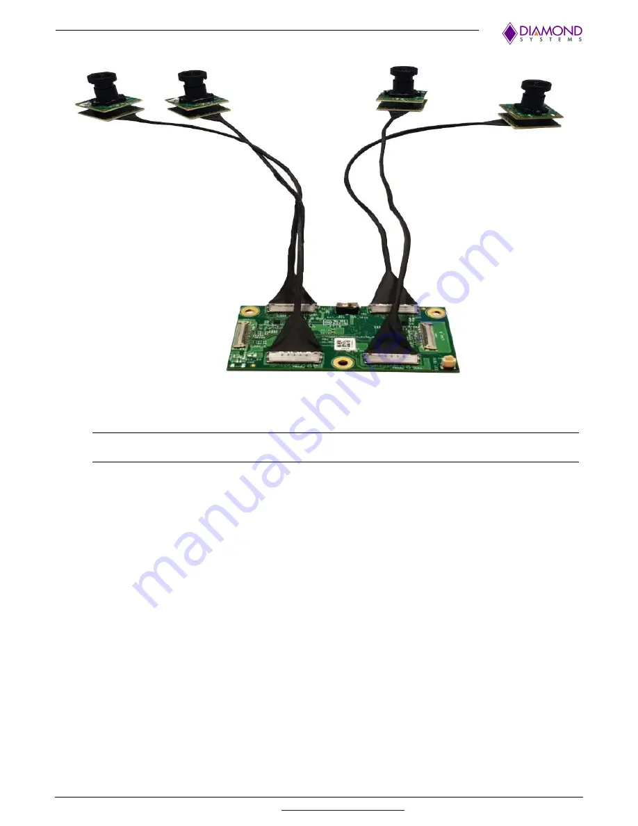
An image of the 4-camera installation is depicted below.
6. Power-on the system.
NOTE
: For a successful implementation ensure that the trigger signal range conforms to 3.3V or 5V. A
voltage signal greater than 5V will cause permanent damage to the chip.
The synchronous mode is a special feature of the e-CAM130_CUXVR board that synchronizes all the
captured camera frames according to the integrated PWM pulse within the trigger functionality. This PWM
trigger pulses can be implemented internally using the Internal Trigger Mode, or externally using the External
Trigger Mode.
7. Switch
SW1
to
EXT_TRIG
position when providing
PWM
trigger signal from an external source.
When using an internal
PWM
trigger signal, the
SW1
switch must remain in the
INT_TRIG
position
This calibrates frames in a synchronous mode.
8. Enter the following command line to access the cameras and begin the streaming process:
gst-launch-1.0 v4l2src device=/dev/video0 ! "video/x-
raw,format=(string)UYVY, width=(int)3840, height=(int)2160" !
nvvidconv ! "video/x-
raw(memory:NVMM),format=(string)I420,width=(int)1920,
height=(int)1080" ! nvoverlaysink overlay-w=1920 overlay-h=1080
sync=false


