background image

ZL0067-0B 

PAGE 20 

©2011 Veris Industries   USA 800.354.8556 or +1.503.598.4564 / support@veris.com  

03112

Alta Labs, Enercept, Enspector, Hawkeye, Trustat, Veris, and the Veris ‘V’ logo are trademarks or registered trademarks of  Veris Industries, L.L.C. in the USA and/or other countries.

TM

E51

INSTALLATION GUIDE

E51C2 FDS

E51C3 L

og

Regist

er

R/W NV Format Units Scale

Range

Description

Configuration

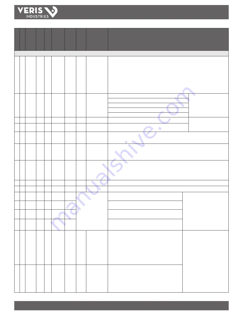
• 129

R/W

UInt

N/A

Reset:
- Write 30078 (0x757E) to clear all Energy Accumulators to 0 (All). 
- Write 21211 (0x52DB) to begin new Demand Sub-Interval calculation cycle. Takes effect at the end of the 

next 1 second calculation cycle. Write no more frequently than every 10 seconds.

- Write 21212 (0x52DC) to reset Max Demand values to Present Demand Values. Takes effect at the end of 

the next 1 second calculation cycle. Write no more frequently than every 10 seconds.

- Write 16640 (0x4100) to reset Logging (E51C3 only).
- Write 16498 (0x4072) to clear Pulse Counts to zero. 
- Read always returns 0.

• 130

R/W NV UInt

10,
11,
12,
31,
40

Single Phase: A + N

System Type
(See Manual. Note: only the 

indicated phases are monitored 

for Phase Loss)

Single Phase: A + B
Single Split Phase: A + B + N
3 phase ∆, A + B + C, no N
3 phase Y, A + B + C + N

• 131

R/W NV UInt

Amps

1-32000

CT Ratio – Primary

Current Inputs

• 132

R/W NV UInt

1, 3

CT Ratio – Secondary  Interface (1 or 1/3 V, may not be user 

configurable)

• 133

R/W NV UInt

100

0.01-320.00

PT Ratio:  The meter scales this value by 100 (i.e. entering 200 yields a potential transformer ratio of 2:1). 

The default is 100 (1.00:1), which is with no PT attached. Set this value before setting the system voltage 

(below)

• 134

R/W NV UInt

82-32000

System Voltage:  This voltage is line to line, unless in system type 10 (register 130), which is line to neutral. 

The meter uses this value to calculate the full scale power for the pulse configuration (below), and as full 

scale for phase loss (register 142). The meter will refuse voltages that are outside the range of 82-660 volts 

when divided by the PT Ratio (above).

• 135

R

NV UInt

kW

W

1-32767

Theoretical Maximum System Power – This read only register is the theoretical maximum power the meter 

expects to see on a service. It is calculated by the meter from the System Type (register 130), CT size 

(register 131), and System Voltage (register 134) and is updated whenever the user changes any of these 

parameters. It is used to determine the maximum power the pulse outputs can keep up with. This integer 

register has the same scale as other integer power registers (see register 140 for power scaling).

• 136

R

UInt

Reserved, always returns 0 

• 137

R/W NV UInt

0,1

Display Units: 0 = IEC (U, V, P, Q, S), 1 = IEEE (default: VLL, VLN, W, VAR, VA)

• 138

R

SInt

-4  0.0001
-3  0.001
-2  0.01
-1  0.1
 0  1.0
 1  10.0
 2  100.0
 3  1000.0
 4  10000.0

Scale Factor I (Current)

Scale Factors

Note: These registers contain a 

signed integer, which scales the 

corresponding integer registers. 

Floating point registers are not scaled. 

Scaling is recalculated when the meter 

configuration is changed.

• 139

R

SInt

Scale Factor V (Voltage)

• 140

R

SInt

Scale Factor W (Power) 

• 141

R

SInt

Scale Factor E (Energy) 

• 142

R/W NV UInt

%

1-99

Phase Loss Voltage Threshold in percent of system voltage 

(register 134). Default value is 10 (%). Any phase (as configured 

in register 130) whose level drops below this threshold triggers 

a Phase Loss alert, i.e., if the System voltage is set to 480 V 

L-L, the L-N voltage for each phase should be 277 V. When the 

threshold is set to 10%, if any phase drops more than 10% below 

277 V, (less than 249 V), or if any L-L voltage drops more than 

10% below 480 V (less than 432 V) the corresponding phase loss 

alarm bit in register 146 will be true.

Phase Loss Output

Note: The phases tested are determined 

by the System Type.

• 143

R/W NV UInt

%

1-99

Phase Loss Imbalance Threshold in Percent. Default is 25% phase 

to phase difference. For a 3-phase Y (3 + N) system type (40 in 

register 130), both Line to Neutral and Line to Line voltages are 

tested. In a 3-phase Δ System type (31 in register 130), only Line 

to Line voltages are examined. In a single split-phase (2 + N) 

system type (12 in register 130), just the line to neutral voltage 

are compared.

Summary of Contents for ConnectPort X4 IA

Page 1: ......

Page 2: ......

Page 3: ......

Page 4: ...POWERDASH DAS THREE LINE DIAGRAM ...

Page 5: ...VTs AND CTs DIAGRAM DAISY CHAIN CONNECTION FOR RS 485 2 3 1 4 5 6 CELL TEMPERATURE SENSOR INSTALLATION WEATHER STATION POWERDASH DAS DAS SCHEMATIC ...

Page 6: ...CELL TEMPERATURE SENSOR INSTALLATION VTs AND CTs DIAGRAM DATA COLLECTION OF KYZ PULSE SOCKET METER DAISY CHAIN CONNECTION FOR RS 485 2 3 1 4 5 7 6 WEATHER STATION POWERDASH DAS DAS SCHEMATIC ...

Page 7: ...PVMET 100 2 User s Guide Date 8 10 12 Revision 2 ...

Page 8: ... 2012 by RainWise Inc All rights reserved No part of this work may be reproduced in any form except by written permission of the publisher All rights of translation are reserved PVMET is a trademark of RainWise Inc ...

Page 9: ...10 Serial General 10 RS 232 10 RS 485 10 Modbus 10 REGISTER MAP 10 CHANGING THE MODBUS DEVICE ADDRESS 11 COMMAND MODE 13 COMMAND SET 13 Get Column Headers HEADER 13 Get Current Data NOW 13 Auto Output AUTO 14 Software Reboot REBOOT 14 Version Information VERSION 14 Modbus Device Address MBID 15 Serial Number SERIAL 15 Command Mode EXIT 15 Calculating the Checksum 16 SOFTWARE FIRMWARE UPDATES 18 MI...

Page 10: ...s 20 Power and Communications Cable 20 Electronics 20 HARDWARE SPECIFICATIONS 21 Power Specifications 21 Operating Environment 21 Pyranometer Sensor 21 Ambient Air Temperature Sensor 21 PV Panel Temperature Sensors 21 RS 485 422 Serial Specifications 21 Physical 21 CONTACT INFORMATION 22 WARRANTY 22 ...

Page 11: ...se Inc should be contacted Installing the Weather Station It is suggested that you operate your system at ground level and make sure that all components operate properly prior to installation If any of the components are damaged or malfunctioning upon receipt RainWise should be contacted Site Requirements and Considerations Ambient air temperature and global irradiance can be affected by obstructi...

Page 12: ...asure this quantity the sensor must be adjusted to the appropriate angle This is done by using a 5 32 or 4mm Allen wrench to loosen the adjustable mounting bracket to the correct angle PV Temperature Sensors This sensor is designed to attach directly to any solar panel When placed on the center of the back of the panel it accurately measures the temperature of the panel Prior to installation of th...

Page 13: ...e lid must first be removed Remove the four Philips head screws from the back of the enclosure Once the lid is removed the circuit board is exposed The inside of the enclosure will appear as below When replacing the cover make sure that all installed cables are pinched by the black foam on the bottom of the enclosure This will enable a weather tight seal Connecting External PV Sensor The PV sensor...

Page 14: ...RS 485 Gnd Signal Ground Shield Cable Shield and Drain RS 485 is rated to 4 000 feet 1 200m at 90 kbps The RS 485 port on the PVMET 100 2 is surge protected but not isolated Connecting the Power Supply The power supply is nominally rated for 24VDC but can accept a voltage in the range of 10 to 30VDC The inputs are reverse polarity surge overvoltage and over current protected The power supply is no...

Page 15: ... 9 ...

Page 16: ...Spec_Length uint16 registers N A 65 Length of common model block 0005 0020 16 C Manufacturer String 32 N A N A Rainwise_Inc Well known value 0021 0036 16 C Model String 32 N A N A PVmet 100 Manuf specific value 0037 0044 8 C Options String 16 N A N A 0 Manuf specific value 0045 0052 8 C Version String 16 N A N A 1 Manuf specific value 0053 0068 16 C_Serial Number String 32 N A N A Serial Manuf spe...

Page 17: ...t16 W m 0 N A Some other type Irradiance 0090 0090 1 C_SunSpec_DID int16 N A 0 303 Well known value Uniquely identifies this as a SunSpec Back of Module Temperature Model 0091 0091 1 C_Sunspec_Length int16 N A 0 2 Variable length model block 5 n where n number of sensors blocks 0092 0092 1 E_BOM_Temp_1 int16 C 1 Measured Back of module temperature 0093 0093 1 E_BOM_Temp_2 int16 C 1 Measured Back o...

Page 18: ...dress you must know the current device address If you do not know the address and cannot scan for it you will have to use the Command Mode The command mode requires a PC and does not require an address It can only be used with a point to point RS 485 connection ...

Page 19: ...ay not be chained together Commands are not case sensitive Command Set Get Column Headers HEADER Description Returns a series of comma delimited text descriptions These descriptions are used to identify the type and order of the returned data in both NOW and DOWNLOAD commands Values None Syntax HEADER Sample Response HDR AIR TEMP PV TEMP1 PV TEMP2 SOLAR CHIP_TEMP 213 Key HDR Identifier HDR Header ...

Page 20: ...outputs current data every second This is equivalent to issuing the NOW command every second This mode will exit upon reception of any character If no data is received from the weather station the units will not output Values None Syntax AUTO Sample Response OK Software Reboot REBOOT Description Forces a soft reboot of the interface On boot up the version information is output Values None Syntax R...

Page 21: ...nse 60 Sample Write Response OK Serial Number SERIAL Description The serial number of the device can be viewed or changed using this command The serial number string is returned in SunSpec Common block Values character string 31 character limit Syntax Read SERIAL Syntax Write SERIAL ABC123 Sample Read Response ABC123 Sample Write Response OK Command Mode EXIT Description Exits from the command mod...

Page 22: ... return line feeds are not included All characters are included in the calculation up until but not including the exclamation character The checksum is represented as a hexadecimal number The following C example code can be used to calculate the checksum Global Variables unsigned short int acc Initialize Accumulator void crc16Init void acc 0 Add byte void crc16Add unsigned short int _data unsigned...

Page 23: ... 17 Return CRC accumulator unsigned short int crc16Acc void unsigned short int tmp acc retval crc16Add 0 crc16Add 0 add two zeros to get a valid crc retval acc acc tmp restore acc return retval ...

Page 24: ...sing a Windows based program called IAPflash This program is supplied with the enc file along with instructions Windows is required to perform updates No other operating systems are currently supported Minimum System Requirements The PVMET 100 2 is equipped with an RS 485 serial port RS 485 422 Baud rate 9600 bps Parity None Data bits 8 Stop bits 1 Interface mode 2 wire half duplex Software The PV...

Page 25: ... Any salt deposits should be dissolved and removed with vinegar and a soft cloth or q tip Dust and other organic deposits are best removed with water rubbing alcohol or window cleaner Never use an abrasive cleaner on the lens Calibration Research indicates that the pyranometer output increases about 1 per year because of changes in the optical transparency of the diffusion disk The station can be ...

Page 26: ... RoHS Compliant IP65 Rated Outdoor Enclosures UL 94 V 2 Body Polycarbonate Pyranometer Sensor RoHS Exempt Body Anodized Aluminum with Cast Acrylic Lens Cable Santoprene Jacket Ambient Air Temperature Sensor RoHS Compliant PV Panel Temperature Sensors RoHS Compliant Body Anodized Aluminum Adhesive Tape Acrylic Titanium Diboride and Aluminum Cable Polyvinyl Chloride Jacket Power and Communications C...

Page 27: ...bient Air Temperature Sensor Range 40 to 80 C 40 to 176 F Accuracy 0 4 C 0 72 F Thermal Time Constant 30 sec PV Panel Temperature Sensors Range 40 to 80 C 40 to 176 F Accuracy 0 3 C 0 54 F Thermal Time Constant 270 sec Cable Length 7 62m 25 ft RS 485 422 Serial Specifications Mode 2 wire half duplex Connector 4 position screw terminal Max Speed 9600 bps Max Modbus Poll Rate 100 ms Termination 120 ...

Page 28: ...pair service and will not reimburse the consumer for damage resulting from warranty service performed by a non authorized repair service No responsibility is assumed for any special incidental or consequential damages To return a unit under this warranty call 800 762 5723 within the continental US or 207 288 5169 The service department will document the need for repair replacement and arrange such...

Page 29: ......

Page 30: ......

Page 31: ......

Page 32: ......

Page 33: ......

Page 34: ......

Page 35: ...L N CE Maximums 300 V L N 520 V L L Metering Over Range 20 Impedance 2 5 MΩ L N 5 MΩ L L Frequency Range 45 to 65 Hz InputCurrentCharacteristics CT Scaling Primary Adjustable from 5 A to 32 000 A Measurement Input Range 0 to 0 333 VAC or 0 to 1 0 VAC 20 over range Impedance 10 6 kΩ 1 3 V mode or 32 1 kΩ 1 V mode ControlPower AC 5 VA max 90V min UL Maximums 600 VL L 347 VL N CE Maximums 300 V L N 5...

Page 36: ...n installing the device DATA OUTPUTS Signed Power Real Reactive and Apparent 3 phase total and per phase Real and Apparent Energy Accumulators Import Export and Net 3 phase total and per phase Reactive Energy Accumulators by Quadrant 3 phase totals and per phase Configurable for CT PT ratios system type and passwords Diagnostic alerts Current 3 phase average and per phase Volts 3 phase average and...

Page 37: ...h with the outside edge of the housing 2 Snap the clips onto the DIN rail See diagram of the underside of the housing below Clipflushwith outsideedge Snaponto DINrail Insertclipsfrominside 3 To prevent horizontal shifting across the DIN rail use two Veris AV02 end stop clips B ScrewMounting 1 Attach the mounting clips to the underside of the housing by sliding them into the slots from the outside ...

Page 38: ...puts are valid which are to be ignored and if neutral is connected Setting the correct System Type prevents unwanted energy accumulation on unused inputs selects the formula to calculate the Theoretical Maximum System Power and determines which phase loss algorithm is to be used The phase loss algorithm is configured as a percent of the Line to Line System Voltage except when in System Type 10 and...

Page 39: ...X1 White Black White Black White Black L1 N L2 L3 X2 X1 A B C N A B C X2 X1 X2 X1 White Black White Black White Black Diagram4 3 Phase3 Wire3CTnoPT Diagram5 3 Phase4 WireWyeDirectVoltageInputConnection3CT USESYSTEMTYPE11 2L USESYSTEMTYPE12 2L 1n USESYSTEMTYPE31 3L USESYSTEMTYPE40 3L 1n USESYSTEMTYPE10 1L 1n White Black White Black White Black L1 N L2 L3 X2 X1 A B C N A B C X2 X1 X2 X1 Diagram6 3 P...

Page 40: ...antinstallations thelinesmustbeneutral earth referencedatlessthan300VACL N TheControlPowerTransformermaybewiredL NorL L Outputtomeetmeterinputrequirements DCControlPowerfrom125VDCto300VDC ULandCEmax FuseRecommendations Keep the fuses close to the power source obey local and national code requirements For selecting fuses and circuit breakers use the following criteria Current interrupt capacity sho...

Page 41: ...e first screen a to the CT V screen Use the or buttons to select the voltage mode Current Transducer output voltage b to the CT SZ screen and through the digits Use the or buttons to select the CT size in amps c back to the S CT screen 7 to the S SYS Set System screen a to the SYSTM screen Use the or buttons to select the System Type see wiring diagrams b back to the S SYS screen 8 Optional to the...

Page 42: ...Thecontactsareopenwhenthe meterispoweredandnophaselossalarmconditionsarepresent PowerSource 3 30VDC 6 30VAC PowerSource 3 30VDC 6 30VAC Over CurrentProtective Device notsupplied UI MENU ABBREVIATIONS DEFINED The user can set the display mode to IEC or IEEE notation in the SETUP menu Main Menu IEC IEEE Description D D Demand MAX M Maximum Demand P W Present Real Power Q VAR Present Reactive Power S...

Page 43: ...l Power Demand P M KW MKVAR M KVA Maximum Apparent Power S Export Demand Maximum Reactive Power Q Export Demand Maximum Real Power P Export Demand DKVAR Present Reactive Power Demand Q D KVA Present Apparent Power Demand S DEMND Demand Scroll When Idle Total Import Real Energy A KWh 3 KWh B KWh C KWh Total Export Real Energy A KWh 3 KWh B KWh C KWh _PHAS M KW MKVAR M KVA Maximum Apparent Power S I...

Page 44: ... M KS Maximum Apparent Power S Export Demand Maximum Reactive Power Q Export Demand Maximum Real Power Export Demand D KQ Present Reactive Power Demand D KS Present Apparent Power Demand DEMND Demand Scroll When Idle Total Import Real Energy A KPh 3 KPh B KPh C KPh Total Export Real Energy A KPh 3 KPh B KPh C KPh _PHAS M KP M KQ M KS Maximum Apparent Power Import Demand Maximum Reactive Power Impo...

Page 45: ...SN RS Serial Number Reset System Operating System ALERT INFO PLOSS A b C LOWPF A b C F ERR A I OVR A b C V OVR A b C PASWD 00000 PASWD 00000 Model Number Energy Pulse Output Error Overrun Error ConF Configuration Error PULSE Error ENERG rES Reset Energy Accumulators to 0 Unit Information Alert Status check if Wrench on LCD RESET Enter Reset Password Enter Setup Password To ENRGY To DEMND COUNT rES...

Page 46: ...3 CT SZ 100 SYSTM 3L 1n 3L 2L 1n 2L 1L 1n Back To SETUP Back Back Back S COM To Setup p 2 SPLOS Next S PT Set Potential Transfomer Ratio RATIO Potential transformer step down is RATIO 1 Default is 1 1 No PT installed See Install for wiring diagrams This value must be set before the System Voltage if used Potential Transformer RATIO 001 00 Back S V Back Sytem Voltage Next Set System Voltage V LL Th...

Page 47: ... pulse output configuration error bit in the Modbus Diagnostic Alert Bitmap if equipped Wh P Set Pulse Energy In Watt Hours VAR Hours if present per Pulse When moving down to a smaller energy the meter will not allow the selection if it cannot find a pulse duration that will allow the pulse output to keep up with Theoretical Maximum System Power see S_PWR screen When moving up to a larger energy t...

Page 48: ...quivalent 600V 120Ωterminatoronthe firstandlastdeviceof thedaisychain Shieldwire NOTES The terminal s voltage and current ratings are compliant with the requirements of the EIA RS 485 communications standard The RS 485 transceivers are unit load or less RS 485 has a 47 kOhm pull up to 5V and RS 485 has a 47 kOhm pull down to Shield RS 485 signal ground Wire the RS 485 bus as a daisy chain from dev...

Page 49: ...er is in data logging mode Changing this value from 0 to 1 through 10 switches the meter to reading mode and selects a buffer to read Data from the selected buffer appears in registers 8000 to 13760 Read WriteCollision If the demand sub interval timeout occurs while the user is reading a page register 158 0 the log data will be held in RAM until the next demand subinterval At that time both the sa...

Page 50: ...ower Meter RESET SYSTEM RUNNING RS Version x xxx last 2 bytes CRC 0x2B Read Device Identification BASIC implementation 0x00 0x01 and 0x02 data Conformity Level 1 Object values 0x01 Veris Industries 0x02 E51xx 0x03 Vxx yyy where xx yyy is the OS version number reformatted version of the Modbus register 7001 Firmware Version Operating System If register 7001 12345 then the 0x03 data would be V12 345...

Page 51: ...ong kVAh E 0 to 0xFFFFFFFF Apparent Quadrants 1 4 Import MSR 018 LSR 019 R NV ULong kVAh E 0 to 0xFFFFFFFF Apparent Quadrants 2 3 Export MSR 020 LSR 021 R SInt kW W 32767 to 32767 Total Instantaneous Real P Power 022 R SInt kVAR W 0 to 32767 Total Instantaneous Reactive Q Power 023 R UInt kVA W 0 to 32767 Total Instantaneous Apparent S Power vector sum 024 R SInt Ratio 0 0001 10000 to 10000 Total ...

Page 52: ...ULong kVARh E 0 to 0xFFFFFFFF Accumulated Q1 Reactive Energy Phase A MSR Import Accumulated Reactive Energy Qh Per Phase 056 LSR 057 R NV ULong kVARh E 0 to 0xFFFFFFFF Accumulated Q1 Reactive Energy Phase B MSR 058 LSR 059 R NV ULong kVARh E 0 to 0xFFFFFFFF Accumulated Q1 Reactive Energy Phase C MSR 060 LSR 061 R NV ULong kVARh E 0 to 0xFFFFFFFF Accumulated Q2 Reactive Energy Phase A MSR 062 LSR 0...

Page 53: ... R SInt kW W 32767 to 32767 Real Power P Phase B 093 R SInt kW W 32767 to 32767 Real Power P Phase C 094 R SInt kVAR W 32767 to 32767 Reactive Power Q Phase A Reactive Power Q 095 R SInt kVAR W 32767 to 32767 Reactive Power Q Phase B 096 R SInt kVAR W 32767 to 32767 Reactive Power Q Phase C 097 R UInt kVA W 0 to 32767 Apparent Power S Phase A Apparent Power S 098 R UInt kVA W 0 to 32767 Apparent P...

Page 54: ... by the PT Ratio above 135 R NV UInt kW W 1 32767 Theoretical Maximum System Power This read only register is the theoretical maximum power the meter expects to see on a service It is calculated by the meter from the System Type register 130 CT size register 131 and System Voltage register 134 and is updated whenever the user changes any of these parameters It is used to determine the maximum powe...

Page 55: ...t voltage to determine frequency Bit 7 Reserved for future use Bit 8 Phase Loss A Bit 9 Phase Loss B Bit 10 Phase Loss C Bit 11 Low Power Factor on A with one or more phases having a PF less than 0 5 due to mis wiring of phases Bit 12 Low Power Factor on B Bit 13 Low Power Factor on C Bit 14 Energy pulse output overrun error The pulse outputs are unable to keep up with the total real power registe...

Page 56: ...interval and then writes the saved data to the log as well as the data for that interval This bit is cleared to 0 on the first demand interval with Logging Page Register 0 Bit 2 Log Buffer Read Collision 2 Set to 1 on the 2nd attempt to save log data while the user is reading the log Logging Page Register is set to something other than 0 At this point the meter ignores the read condition and does ...

Page 57: ...ted Real Energy Net Import Export Accumulated Real Energy Ph Clear via register 129 259 260 R NV Float kWh Real Energy Quadrants 1 4 Import 261 262 R Float kWh Real Energy Quadrants 2 3 Export 263 264 R Float kVARh Reactive Energy Quadrant 1 Lags Import Real Energy IEC Inductive IEEE Accumulated Reactive Energy Qh Quadrants 1 2 Import Quadrants 3 4 Export 265 266 R Float kVARh Reactive Energy Quad...

Page 58: ...ulated Q1 Reactive Energy Phase A Quadrant 1 Import Accumulated Reactive Energy Qh 331 332 R Float kVARh Accumulated Q1 Reactive Energy Phase B 333 334 R Float kVARh Accumulated Q1 Reactive Energy Phase C 335 336 R Float kVARh Accumulated Q2 Reactive Energy Phase A Quadrant 2 337 338 R Float kVARh Accumulated Q2 Reactive Energy Phase B 339 340 R Float kVARh Accumulated Q2 Reactive Energy Phase C 3...

Page 59: ...he IEEE 754 32 bit specifications SunSpecCompliantCommonandMeterModelRegisterBlocks See www sunspec org for the original specifications E51C2 FDS E51C3 Log Register R W NV Format Units Scale Range SunSpec Name Description SunSpec 1 0 Common Model 40001 R NV ULong 0x5375 6e53 C_SunSpec_ID ASCII SunS Identifies this as the beginning of a SunSpec Modbus point 40002 40003 R NV UInt 1 C_SunSpec_DID Sun...

Page 60: ...SInt 1 M_AC_Voltage_SF AC Voltage Scale Factor Frequency 40086 R SInt Hertz M_AC_Freq_SF 32767 to 32767 M_AC_Freq AC Frequency 40087 R NV SInt SF 1 M_AC_Freq_SF AC Frequency Scale Factor Power Real Power 40088 R SInt Watts M_AC_Power_SF 32767 to 32767 M_AC_Power Total Real Power sum of active phases 40089 R SInt Watts M_AC_Power_SF 32767 to 32767 M_AC_Power_A Phase A AC Real Power 40090 R SInt Wat...

Page 61: ...R NV ULong VA hours M_Energy_VA_SF 0x0 to 0xFFFFFFFF M_Exported_VA_A Phase A Exported Apparent Energy 40128 40129 R NV ULong VA hours M_Energy_VA_SF 0x0 to 0xFFFFFFFF M_Exported_VA_B Phase B Exported Apparent Energy 40130 40131 R NV ULong VA hours M_Energy_VA_SF 0x0 to 0xFFFFFFFF M_Exported_VA_C Phase C Exported Apparent Energy 40132 40133 R NV ULong VA hours M_Energy_VA_SF 0x0 to 0xFFFFFFFF M_Imp...

Page 62: ...ort_VARh_Q4 Quadrant 4 Total Exported Reactive Energy 40167 40168 R NV ULong VAR hours M_Energy_VAR_SF 0x0 to 0xFFFFFFFF M_Export_VARh_ Q4A Phase A Quadrant 4 Total Exported Reactive Energy 40169 40170 R NV ULong VAR hours M_Energy_VAR_SF 0x0 to 0xFFFFFFFF M_Export_VARh_ Q4B Phase B Quadrant 4 Total Exported Reactive Energy 40171 40172 R NV ULong VAR hours M_Energy_VAR_SF 0x0 to 0xFFFFFFFF M_Expor...

Page 63: ... inaccurate Incorrect setup values Verify the values entered for power meter setup parameters CT and PT ratings system type etc See the Setup section Incorrect voltage inputs Check power meter voltage input terminals to verify adequate voltage Power meter is wired improperly Check all CTs and PTs to verify correct connection to the same service CT and PT polarity and adequate powering See the Wiri...

Reviews: