Technical Manual Cold Storage Controllers TKP / TKC x130 - x140
Page 9
'Physical' and 'virtual' sensors
1
. Each 'physical' (real) sensor is able to fulfill up to 3
functions at the same time (see Assignment Page),
any sensor is able to do the same job.
Up to 6 control sensors can be assigned the same
time. The warmest of them initiates the cooling
function.
2
. It is possible to create a 'virtual' sensor to realize
different kinds of averaging, e.g. multiple sensors in
a huge room or averaging of inlet and outlet sensor
in a chest freezer. The 'virtual' sensor resp. value
(
sensor 7
) follows from the selectable emphasis of
the sensors which must have an effect on the result
(
weighting 1-6
, Assignment Page). The functions
assigned to this 'sensors' (
funct sens. 7a-c
, As-
signment Page) are the same as the functions for
the 'physical' sensors.
Example
: If the 'physical' sensor 1 got the function
"
con
" (control sensor) and also the 'virtual' sensor,
then the warmer one initiates refrigeration.
● Selection of a "virtual sensor":
- Assignment of a function by "
funct sens7a-c
"
● Selection of a 'physical' sensor which must have
an effect on the result :
- Activating of the sensor by assigning a
function (e.g. display only sensor)
● Set weighting for the selected sensor
(
weighting 1-6
).
The sum of all emphasis values must be
100%.
Example
:
If sensor 1 and sensor 2 must have an effect on
the result and you set "
weighting 1
" to "30%"
and "
weighting 2
" to "60%", then you get the error
message "
SEL
" (assignment error).
Further causes for the error message "
SEL
"
● The sum of all emphasis parameters is 100%,
but no virtual sensor function is selected
● All 4 emphasis values are set to '0' and a
'virtual' sensor function is assigned
● A physical sensor is switched off, but an
emphasis value > 0 is selected.
Example 1, Chest Freezer:
For the detection of the actual value, inlet and outlet
sensor must be used. Sensor 1 is mounted at the
suction side (inlet) and must have an 60% influence
on the result. Sensor 2 is mounted at the outlet and
must have an 40% influence.
- set "
weighting 1
" to "60"
- set "
weighting 2
" to "40"
- set "
funct sensor 7a
" to "con" (control sensor)
Example 2, huge room, standard application
Sensors 1-3 must measure the rooms temperature,
an arithmetic average must be calculated, sensor 4 is
the defrost limitation sensor in the evaporator.
- set "
weighting 1+2
" to "33" and "
weighting 3
"
to "34"
- set "
funct sensor 7a
" to "con" (control sensor)
- set "
funct sensor 4a
" to "df1"
Special Function
If an emphasis parameter value is set to
100% (others to 0), up to 6 functions can
be assigned to the corresponding physical sensor.
This may be of interest for applications where
more than 3 sensor functions are used.
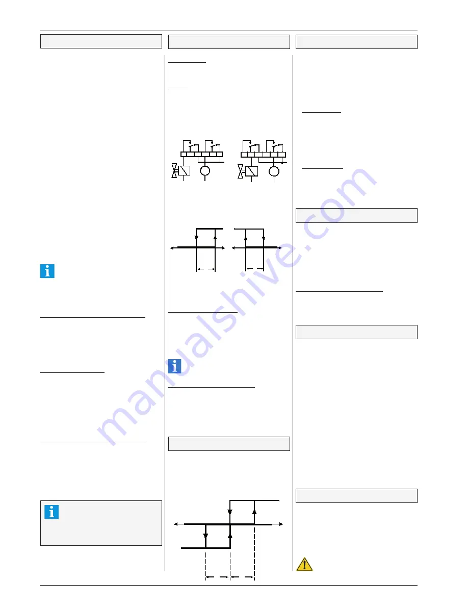
M
L
M
L
cool.
mode
freez..
refrig relay fan relay
refrig relay fan relay
cool.
mode
refrig.
Caution
Cooling
Control circuits
This controller is able to control up to 4 independent
cooling circuits, each with an own setpoint.
Cooling
Cooling is controlled by switching the output relay.
In case of power loss or controller defects the
contacts must switch in a position which is safe for
the application. For this reason we are using the
N/O-contact for refrigeration applications (fail-safe:
open contacts). For freezing applications we use
the N/C-contacts (fail-safe: closed contacts).
This can be set by parameter
"cooling mode"
(mode page). The point of cut-off is always the
valid setpoint. The selection of this parameter
also affects to the switching characteristic of the
fan relay.
The refrigeration relay can be disabled via interface
(see chapter "networking via E-Link").
Low temperature Limitation
Can be used e.g. for refrigerated shelfs with roller
blinds to limit the temperature at the air outlet du-
ring night operation. When the temperature at the
alarm sensor falls below the limit set by "
warn low
limit
" (Setpoint page) cooling will switch off. This
value is the threshold for the undertemperature
alarm at the same time.
The undertemperature limitation cannot
be switched off and is also active with
disabled low temperature warning.
Refrigeration delay after power up
The start of refrigeration after power-up resp.
mains loss can be delayed by parameter "
re-
frDlyAftMnsOff
" (Setpoint Page). In plants with
many cold storages this function prevents that
after power-up all solenoid valves open at the
same time, even though not enough machine
power is present yet.
freezing
relay ON
cooling =
relay OFF
warm
cold
setpoint
Hysteresis
cooling = relay ON
cold
warm
setpoint
hysteresis
relay OFF
refrigeration
notice
Heating function
For one relay it is possible to assign the function
of heating circuit 1. The setpoint is the cut-off of
heating and cooling at the same time:
•
for cooling at se hysteresis
and
• for heating at setpoint - hysteresis.
refrig. ON
heating ON
cold
warm
OFF
setpoint
hysteresis
hysteresis
Runtime Monitoring
The controller monitors the total running hours per
day of the cooling outputs. This values are displayed
under parameters „
run time refr. x
“ for each circuit.
One day counts from the time of the parameter
„
runtime mess at
“ (mode page) until the same time
of the next day.
Example:
"
runtime mess at
" set to 11:00.
Monitoring time range is from 11:00 o'clock day 1up
to 10:59 o'clock day 2.
The total runtime of the cooling relays over a day
will be stored and displayed (
"runtime refr. 1-4"
,
Actual Values).
A parameter „
cooling limit
“ can be set to a reasonable
value (hours per day) which, when exceeded on
three days in a sequence, will cause an alarm at
the hour programmed by „
runtime mess at
“. Then
the alarm relay will be de-activated and the alarm
LED goes on.
This alarm will be cancelled automatically 1
hour later.
Operation with a single compressor
If a single compressor is controlled by a refrigeration
relay, it is suggestive to have an idle time to prevent
the machine from damages caused by short cycle
operation. The compressor can restart only after the
timer "
compr. pause
" (setpoint page) is run down. The
remaining time up to the compressors restart can be
read at "
rem.compr pause X
" (actual page).
If a compressor must be controlled directly,
never use the cooling mode 'freezing' to
prevent compressor damages by conti-
nuous running!
Second setpoint (night operation)
For each of the 4 circuits a second setpoint is avai-
lable (
2nd setp Ch X
). This can be used for night
operation or other energy savings. The toggling
between these setpoints can be made by the internal
clock or by a digital input. The setpoint which is in
use at the moment is marked by two arrows like:
„—> -20,0°C <—“. In the actual values page you
see also if day or night setpoint is in use.
Internal toggling
The parameters „
night setpt ON
“ (mode page)
and „
night setpt OFF
“ determine the period
when the 2nd setpoint will be active. If the
function 'night settings' is assigned to one of the
digital inputs, it must be connected to mains
phase. If the internal timer is not used, set
'
night setp. ON
' and
'night setp. OFF
' times to
„OFF“.
External toggling
If the 'night settings' input is open, the 2nd
setpoint is activated all time and the internal
timer is disabled. With this digital input to mains
phase, the normal (1st) setpoint is activated
and internal timer is enabled.
Second Set of Setpoints
The controller offers two sets (layers) of setpoints,
where the first layer of setpoint is used during normal
operation and the alternative layer of setpoints with
other temperatures is used e.g. for other products
which will be stored only sometimes. For each layer
there are parameters for the setpoints, the night
setpoints, warning offsets and low temperature
warning. The names of the second set parameters
begin with '
alt
....'.
Toggling between the setpoint layers
1. internal: with parameter „
setpoint layer
“
2. external: assign function „setpoint layer“ to
a digital input. If connected to mains
phase, the 2nd layer is in use.


