


ETK-S6.0 - User’s Guide
19
ETAS
Hardware Description
• 1 reset line which allows the ETK to control the system reset of the ECU
• Voltage and ground lines
– 2 ECU voltage lines, which are not used for ETK power supply but only
for detection of the ECU status, therefore the power consumption on
these lines is negligible (refer to chapter 4.6 on page 22)
– 6 ground lines for a proper shielding of the ECU interface lines.
If the debug interface lines between the ETK-S6.0 and the ECU microcontroller
are configured as an H-UDI interface at least two GPIO pins are required: the
usage of the DAI1/ DAI2 signals is mandatory, if more trigger options are
required the DAI3/ DAI4 signals can be additionally applied.
ECU and ETK DAI Port Voltage Level
The DAI ports of the ECU and the DAI ports of the ETK are normally not on the
same voltage level. To use the H-UDI Debug interface it is necessary to shift the
voltage levels at the ECU. There are two methods for shifting the voltage level:
• usage of level shifter ICs (monolithic implementation)
• usage of diodes and resistors (discrete implementation).
The voltage level of the DAI ports of the ECU (5 V) has to be shifted to the volt-
age level of the DAI ports of the ETK system controller (3.3 V).
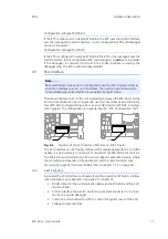
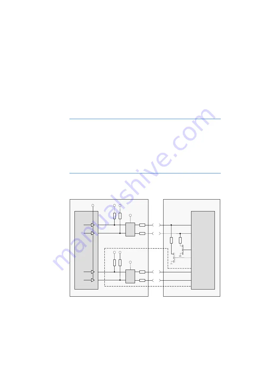
Recommended Voltage Level Shifting Method
It is recommended to use level shifter ICs (e.g. 74CB3T3306) to shift the voltages
of the DAI ports of the ECU and of the DAI ports of the ETK at the same level (see
Fig. 4-4 on page 19).
Fig. 4-4
Usage of level shifter ICs
3k3
3k3
ECU
ETK
PV
CC
(5V)
22
22
33k
33k
5V
3.3V
Level
Shifter
(e.g. 74CB
3T3306)
V
CC
(3.3V)
PV
CC
(5V)
22
22
33k
33k
5V
3.3V
Level
Shifter
(e.g. 74CB
3T3306)
V
CC
(3.3V)
Optional
PV
CC
(5V)
PV
CC
(5V)
DAI1
DAI2
Micro-
controller
DAI1
DAI2
PV
CC
(5V)
DAI3
DAI4
DAI3
DAI4
System
Controller


