background image

Parallel Poll, PPØ

The counter does not have any parallel poll facility.

Device Clear, DC1

The controller can reset the counter, forcing it to default
settings, via interface message DCL (Device clear) or
SDC (Selective Device Clear).

Device Trigger, DT1

You can start a new measurement from the controller via
interface message GET (Group Execute Trigger).

Bus Drivers, E2

The GPIB interface has tri-state bus drivers.

Connecting the Controller

The bus interface connector is on the rear panel of the
counter. If your counter does not have any connector, you
must install the GPIB-interface option, see installation.

Connect the controller via an IEEE-488 cable to the bus
connector. If you use IEC-625 cables, an adapter is avail-
able, see ordering information at the end of this manual.

Giving the Counter an
Address

The counter must have a unique address so that the con-
troller can communicate with it. The address is selected
by setting switches to the binary equivalent of the address
you want. The switches are located to the right of the inter-
face connector. The OFF position means 0 and the ON po-
sition means 1.

Ad-
dress

Switch
settings

Ad-
dress

Switch
settings

Ad-
dress

Switch
settings

0

00000

10*

01010

20

10100

1

00001

11

01011

21

10101

2

00010

12

01100

22

10110

3

00011

13

01101

23

10111

4

00100

14

01110

24

11000

5

00101

15

01111

25

11001

6

00110

16

10000

26

11010

7

00111

17

10001

27

11011

8

01000

18

10010

28

11100

9

01001

19

10011

29

11101

30

11110

*Factory setting.

NOTE:

31 is the bus command for “Untalk” and should not
be used. If 31 is selected the counter will work as
if address 0 is selected.

Talk-Only

The leftmost switch in the address switch block is the
TALK ONLY switch. If you set it to ‘1’, the counter will out-
put measurement results on the bus continuously. It will
not react to any incoming commands.

This setting may only be used if the counter is connected
to a ‘Listen only’ device such as a printer. Set the switch to
‘0’ when you want normal bus communication.

Talk only is set to ‘0’ on delivery.

The counter is now ready for bus control.

Checking the Communication

To check if the counter and the controller can communi-
cate, address the counter and execute the following se-
quence: (The programming example is for an HP-85 con-
troller.)

Type on controller:

This should happen.

REMOTE

710

The remote indicator
should be switched on.

OUTPUT

710;"ID?"

Ask for the counter identity.

ENTER

710;A$

Input result from counter.

DISP

A$

The response on the
display of the controller is
the identity of the counter.

If everything is OK, the counter will identify itself as:

PM6666/YZW/MN

where:
Y =

4 if the counter has an HF-input, otherwise 0.

Z =

3 for MTCXO, otherwise 1

W =

6 (GPIB-bus is installed)

M =

Revision No. of counter firmware

N =

Revision No. of GPIB-bus firmware

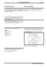
GPIB connector

Address switch

10MHz 0.5-15Vrms

EXT REF INPUT

VOLTAGE

SELECTOR

PM 9604

INCLUDED OPTIONS

PM 9605
PM 9607

PM 9608B

IEEE 488 INTERFACE

TALK ONLY

ADDRESS

16 8 4 2 1

ON

O

F F

SUPPORTED

FUNCTIONS:
SH1,AH1

T5,L4
SR1,RL1

DC1,DT1
E2

THERMAL FUSE IN

MAINS TRANSFORMER

Figure 8

GPIB connector and address switch, the
numbers above the switches indicate the sig-
nificance of each switch.

Page: 24

GPIB-INTERFACE OPERATION

PM 6666 - OPERATORS MANUAL

Summary of Contents for PM 6666

Page 1: ...rogramming 25 Syntax 25 Selecting output separator 26 How to select function 26 Selecting Measuring Time 27 Selecting Input settings 27 Totalize Start Stop 27 Free Run Triggered 28 Service Request 28...

Page 2: ...EC Low Voltage Directive 73 23 EEC Sample tests Standards used IEC 348 1978 Safety Requirements for Electronic Measuring Apparatus EN 50081 1 1992 Electromagnetic Compatibility Generic Emission Standa...

Page 3: ...rantee period provided that Fluke determines that the product is defective and that the failure has not been caused by misuse alteration or abnormal operation Guarantee service for products installed...

Page 4: ...procedures or practices in order to prevent personal injury Symbols Indicates where the protective ground lead is connected inside the instrument Never un screw or loosen this screw Signal Ground sym...

Page 5: ...r feet T Screws for removing the cover U External reference input BNC connector V Voltage range selector W Power inlet socket X GPIB interface connector optional Y GPIB address selector option MAINS T...

Page 6: ...n is used to decrease the value L Input B BNC connector M Trigger indicators N Attenuator buttons O Slope selection buttons P DC or AC coupling selection buttons Q Large LCD display R Tilting support...

Page 7: ...rface if ordered An HF input if ordered Labels on the rear panel indicate which options are fitted in your Timer Counter Voltage Range Selection Set the Timer Counter to the local line voltage before...

Page 8: ...high stability oscillator and either of the GPIB interface or the Battery unit can be in stalled in one and the same Timer Counter Calibrating the MTCXO The MTCXO Time base can easily be recalibrated...

Page 9: ...control so that the counter counts properly Hold down the CALIB button on the main printed circuit board in the counter and press the Reset button Wait about 20 seconds until the display shows 10 000...

Page 10: ...e One code for each function see below Move function cursor to FREQ A FREQ A FREQ B possible via Bus ON STAND BY HOLD DISPLAY MEASURING TIME 10s 1s 0 2s SINGLE REF EXT MAN TOT A B TOT A B TOT A A B TI...

Page 11: ...he secondary side of the transformer The power cable must be disconnected from the line outlet socket if it is necessary to completely isolate the Timer Counter from the line Error 01 RAM memory error...

Page 12: ...VOLT A MAX MIN LEVEL AUTO LEVEL READ FUNCTION HOLD DISPLAY MEASURING TIME 10s 1s 0 2s SINGLE REF EXT MAN TOT A B TOT A B TOT A A B TIME A B RATIO A PERIOD C FREQ A FREQ FUNCTION COMMON B via A VOLT A...

Page 13: ...if you wish to measure between any other combination of slopes The Timer Counter counts the total number of pulses fed to Input A The positive slope of the Input B signal starts the totalizing and th...

Page 14: ...IN LEVEL AUTO LEVEL READ TIME MEAS TIME MEAS HOLD DISPLAY MEASURING TIME 10s 1s 0 2s SINGLE REF EXT MAN TOT A B TOT A B TOT A A B TIME A B RATIO A PERIOD C FREQ A FREQ FUNCTION COMMON B via A VOLT A M...

Page 15: ...es not close again until the period is completed If you wish to do one measurement instead of repetitive measurements see DISPL HOLD When TOT A B or TOT A B is selected the Measuring time setting will...

Page 16: ...a similar function See GPIB bus operation Connect the signal to INPUT A via a BNC cable Connect the signal to INPUT B via a BNC cable LOCAL RESET START STOP TOTALIZE A HOLD DISPLAY MEASURING TIME 10s...

Page 17: ...process has been finished A new measurement can always be initiated via the RESET button Use this input for all functions except FREQ C Input data Range DC Hz to 160 MHz Impedance 1 M 35 pF Min pulse...

Page 18: ...the button switches on Now the auto level and Read level buttons have the red arrow up and down function Another press will switch off the function NOTE Sensitivity can be set when AC coupled and Tri...

Page 19: ...ensitivity so that the hysteresis band of the Timer Counter is about half the amplitude of the input signal For time measurements Select DC coupling and set the trigger level to the desired level The...

Page 20: ...Not bus controllable READ LEVEL HOLD DISPLAY MEASURING TIME 10s 1s 0 2s SINGLE REF EXT MAN TOT A B TOT A B TOT A A B TIME A B RATIO A PERIOD C FREQ A FREQ FUNCTION COMMON B via A VOLT A MAX MIN LEVEL...

Page 21: ...e and to set trigger level A to the MIN reading plus the 10 of Vpp 5 Depress SET B use and to set trigger level B to the MAX reading minus the 10 of Vpp 6 Select TIME A B This is the HF input which mu...

Page 22: ...ded battery can be restored by cy cling the battery a number of times but a restored battery will never reach the capacity of a new one If you must store your counter for some time without using it st...

Page 23: ...n T5 Listener function L4 Service request SR1 Remote local function RL1 Parallel poll PP Device clear function DC1 Device trigger function DT1 Bus drivers E2 Source and Acceptor Handshake SH1 AH1 SH1...

Page 24: ...Untalk and should not be used If 31 is selected the counter will work as if address 0 is selected Talk Only The leftmost switch in the address switch block is the TALK ONLY switch If you set it to 1 t...

Page 25: ...d consists of a header address ing the function you want and a body instructing the func tion what to do NOTE Some programming commands consists only of the Header e g trigger command X What is a Prog...

Page 26: ...The space be tween FREQ and A indicates the input separator that you always must insert Function Command Comment Frequency A FREQ A Default Frequency C FREQ C Period A PER A Ratio A B RATIO A B Time...

Page 27: ...will be 0 2 V 0 5 V and 1 0 V Trigger level Command Comment Volt TRGLVL num num trigger level in Volts Range 5 10V to 5 10V Minimum increment 0 02 V Default 0 V If ATT10 is selected Trigger level ran...

Page 28: ...hen Free Run is switched on Default Time Out is not indicated on the display When the counter switches to LOCAL Time Out is off but when switched to remote again the set Time Out will be active again...

Page 29: ...when auto triggering is selected If triggered mode is selected the counter waits to be trig gered otherwise it proceeds with the measurement You can have the SRQ mask set for SRQ at ready for trigger...

Page 30: ...put will be as follows Function command Header 3 6 characters same Header as used for selecting the function O when overflow otherwise space Measurement result always 9 digits and a decimal point Same...

Page 31: ...lowed by 12 hexadecimal digits The two letters will tell the controller how to evaluate the twelve hex digits which represent the contents in the internal registers of the counter Formula Multiplier H...

Page 32: ...MTIME number FRUN ON20 TOUT number 20 9 INPA Input A settings TRGSLP POS ATT OFF COUPL AC AUTO OFF TRGLVL number SENS 1 18 17 19 INPB Input settings TRGSLP POS ATT OFF B COUPL DC COM OFF TRGLVL number...

Page 33: ...ring on positive slope TRGSLP NEG Triggering on negative slope COUPL AC AC coupling COUPL DC DC coupling COM ON A and B common via Input A COM OFF A and B separated SENS num num 1 gives 20 mV sensitiv...

Page 34: ...10 F TIME 220 TIME 230 DISP READY ELAPSED TIME F E s 240 SHOW 5 RESULTS 250 DISP FIRST 5 RESULTS 260 FOR K 1 TO 5 270 ENTER Z B 280 GET FORMULA CHARACTER 290 F B 1 1 300 GET MULTIPLYER CHARACTER 310 M...

Page 35: ...program example illustrates the program data out feature of PM 6666 By asking a set of queries the counter responds with its current setup The output format of these answers to the queries is identica...

Page 36: ...nstead of the Fluke PM 2201 interface The following set of device parameters is suitable for a PM 6666 with address 10 The device parameters are set with the configuration program IBCONF see the IBM a...

Page 37: ...x 1010 C A C B Frequency Range Input A 0 MHz to 160 MHz A B 0 MHz to 16 MHz B A C A A B SINGLE 120 MHz to 160 MHz with limited tem perature range typical 23 C 5 C Input B 0 MHz to 16 MHz Input C 70 M...

Page 38: ...ng 10 of Vp p Input A and Input B Frequency Range DC Coupled DC to 160 MHz 120 MHz to 160 MHz with limited temperature range typical 23 C 5 C AC Coupled 20 Hz to 160 MHz 120 MHz to 160 MHz with limite...

Page 39: ...f 0 2s 1s 10s or SINGLE can be selected NOTE When SINGLE is selected together with PERIOD RATIO or TIME the result is a single cycle meas urement but SINGLE together with FREQUEN CY results in a fixed...

Page 40: ...GATE Indicator Indicates that the counter is measur ing REMOTE Indicator Indicates when the counter is re motely controlled via an installed GPIB IEEE 488 interface PM 9604 Cursor Indicates selected m...

Page 41: ...contents of the counting regis ters are transferred to the controller without being proc essed by the counter The processing must be done in the controller instead The output format is FMXXXXXXXXXXXXS...

Page 42: ...nput Frequency Reference Oscillator and Interface Input Frequency Option 0 Standard 160 MHz 4 1 3 GHz PM 9608B 00 Reference Oscillator Option 1 Standard 3 MTCXO PM 9607 00 Interface Option 1 Standard...

Page 43: ...he utmost importance to know how sensitivity is measured Recommended Instruments Signal source with a 50 output impedance 350 MHz oscilloscope with a 50 input impedance BNC T piece Two BNC cables one...

Page 44: ...unter Disconnect the cable from the counter and connect it to the oscilloscope Read the amplitude on the oscilloscope Check that the reading is the same as or less than the sensitivity level in the co...

Page 45: ...removal 8 D DC Selecting 18 Delimiters SEE Separators Device clear 24 Device Trigger 24 Display hold Operating the button 16 Display hold button Location 6 E Earthing SEE Grounding EOI mode SEE Output...

Page 46: ...2 Read level 20 GPIB code 20 Read level button Location 6 Rear feet 5 Remote local 23 Removing the cover 8 Reset Description of function 17 Operating the button 16 Reset button Location 6 S Safety 4 S...

Reviews: