10
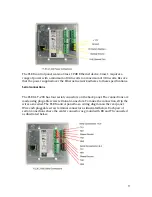
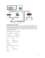
The FLEX control panel uses standard Serial protocols. The standard distance for RS
232 communication is 50 feet using 22 ga. three‐conductor cable. FSR recommends
the use of West Penn 230 series communications wire or similar to ensure proper
signal transmission.
IR
Connections
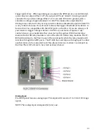
The FLEX system ships with two IR transmitters. The FLEX LT‐200 system can
power up to four units on the LT 200 units and 2 on the LT 100. Using quality 22‐
gauge two‐conductor wire the IR transmitters can be placed up to 100 feet away
from the FLEX panel. Transmitter buds should be placed in front of the IR receiving
window of the device to be controlled. Each pluggable screw terminal connector will
power 2 IR transmitters. Each connector has 2 inputs for each of the (+) wires. The
ground connector is shared.
General
Purpose
I/O
The Flex has 4 GPIO ports. It is important to note that these are different from dry
contact closures and do not have the same functionality. The GPIO ports can be
configured as Inputs or Outputs. As an Input, a voltage of 2.4 VDC to 24 VDC will
read as a 1 while a voltage below +1.0 VDC will read as a 0. When interfaced to TTL
or CMOS logic, the Flex inputs are directly compatible. When interfaced to an “open
collector” type output or normally open contact closure that is active high, make
sure that it is at least 2.4VDC and does not exceed 24VDC when “on”. Additionally, if
using an “open collector” type output that “leaks” more than 0.1 mA, a pull‐down
resistor may be required to keep the Flex input below the 1.0 VDC when the source
is “off” . If you are interfacing to an “open collector” or normally open contact
closure that is active low, attach a “pull‐up” resistor of 1K to 10K ohms between
your GPIO pin and the V+ input of the Flex. This will hold the pin high until your


