background image

 MB2146-450-E Setup Guide 

Chapter 4 Sample Code Manual 

MCU-AN-500072-E-10 – Page


32 


4.2.2  Beep .c 

When  AD  key  is  pressed,  it  will  sound  beep  and  then  it  will  be  off.  All  the  occasions  are 

driven by setting different values for PIN PPG1.  
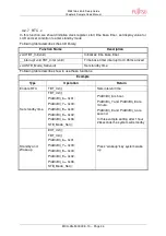
Following table describes the Beep library: 

Function Name 

Description 

void Beep_On(void) 

Make beep to sound out 

void Beep_Off(void) 

Off beep sound 


4.2.3  EEPROM .c 

In  this  function,  all  values  of  EEPROM  are  initialled  to  0x80  and  global  parameters  are 

initialled to 0. 
Following table describes the EEPROM library: 

Function Name 

Description 

void Init_EEProm(void) 

Initializes all global variable and EEPROM to 

its’ value to sub-address number 


4.2.4  Ext-interrupt .c 

In this function external interrupt register are initialled.  
Following table describes the external interrupt library: 

Function Name 

Description 

void EXT_Init(void) 

Initializes external interrupt  

__interrupt void INTER_EXT (void) 

Captures falling edge and generates interrupt 


Summary of Contents for MB2146-450-E

Page 1: ...FUJITSU MICROELECTRONICS SUPPORT SYSTEM MCU AN 500072 E 10 F MC 8FX FAMILY 8 BIT MICROCONTROLLER MB95F310 SERIES MB2146 450 E SETUP GUIDE ...

Page 2: ......

Page 3: ...esentatives 1 F2MC is the abbreviation of FUJITSU Flexible Microcontroller 2 Referring to the following as the EV Board MB2146 450 E is the EV Board for MB95F310 MCU 3 Referring to the following as the BGMA 4 Referring to the following as the SOFTUNE Handling and usage Handling and usage of this product and notes regarding its safe use are described in the manuals for products bundled with the EV ...

Page 4: ... contains many electronic components keep it away from direct sunlight high temperature and high humidity to prevent condensation Do not use or store the product where it is exposed to much dust or a strong magnetic or electric field for an extended period of time Inappropriate operating or storage environments may cause a fault Damage Use the product within the ranges given in the specifications ...

Page 5: ...m the use of information contained herein The products described in this document are designed developed and manufactured as contemplated for general use including without limitation ordinary industrial use general office use personal use and household use but are not designed developed and manufactured as contemplated 1 for use accompanying fatal risks or dangers that unless extremely high safety...

Page 6: ...ction List 8 2 3 IDC10 Interface Description 9 2 4 BGMA USB Configuration 9 2 5 LED Description 12 3 EV BOARD MANUAL 13 3 1 EV board Overview 13 3 2 Function List 14 3 3 EV board Schematic 15 3 4 HW Module Description and Jumper settings 16 3 4 1 Pin Assignment of MB95F310 16 3 4 2 Power Module 17 3 4 3 I2C Module 18 3 4 4 A D Module 18 3 4 5 LCD Module 20 3 5 Operation Manual 21 3 5 1 Mode Switch...

Page 7: ...le Description 31 4 2 1 ADC c 31 4 2 2 Beep c 32 4 2 3 EEPROM c 32 4 2 4 Ext interrupt c 32 4 2 5 I2C c 33 4 2 6 LCD c 33 4 2 7 RTC c 34 4 2 8 UART c 35 4 2 9 delay_try Function 35 4 3 Global Variable Description 36 4 4 How to Add these Library 37 4 5 Usage Demo 37 5 DEVELOPMENT PLATFORM QUICK START 38 5 1 Tools Setup Sequence 38 5 2 Open Project and Start Debug 38 5 3 Operation Precautions 38 ...

Page 8: ...re that the following devices are placed in the package EV board MB2146 450 E 1PCS Hardcopy China RoHS report quick start guide 2PCS 1 2 System Block To set up a debugging system first connect a PC a BGMA and an EV board together shown as follows Figure 1 2 1 System Block 1 3 Handling Precautions The EV Board can be used in connection with its bundled products To ensure use of this product correct...

Page 9: ... light and small BGM Adapter Since a monitor program is performed in exclusive memory space it does not consume user memory space Continuation execution step execution and break correspondence It connects with a host computer by the USB interface 1 5 Hardware Setup In the hardware setup procedure you should configure and connect the hardware products This chapter includes the configuring and conne...

Page 10: ...B95F310 Series MCU MCU MAX machine clock 16 25 MHz MCU power voltage 1 8 1 2 V 3 3 1 V 2 Break pointer 256 software breakpoints 3 USB interface to PC SOFTUNE Compatible to USB protocol version 1 1 4 1 Line UART interface to the MB95F310 Series MCU The Baud rate is 62 500 bps 5 Support the MCU flash programming for engineering development The program and read speed is about 800 B S 1 The value vari...

Page 11: ...et input 4 RSTOUT Target MCU reset output 5 RSV Reserved 6 RSV Reserved 7 RSV Reserved 8 DBG Target MCU debug pin 9 RSV Reserved 10 RSV Reserved 2 4 BGMA USB Configuration The BGMA is provided with a USB cable Connect the BGMA to a PC with a USB cable If the connection is right the following window will pop up Follow the instructions displayed and then click Next Figure 2 4 1 Install BGMA in Windo...

Page 12: ... MCU AN 500072 E 10 Page 10 Select Install from a list or specific location Advanced then click Next Figure 2 4 2 Install BGMA in Windows 2 Select Drivers from the folder where SOFTUNE is installed click Next Figure 2 4 3 Install BGMA in Windows 3 ...

Page 13: ...ed as follows and then click Next Figure 2 4 4 Install BGMA in Windows 4 Windows will install the driver automatically Click Finish after the driver has completed the installation normally Then users can find the BGMA is recognized as MB2146 08 in Windows system Figure 2 4 5 BGMA is installed in Windows ...

Page 14: ...B cable is plugged to PC check the Power LED turning Green or not Refer to Figure 2 5 1 Figure 2 5 1 BGMA Power LED 1 Second plug IDC10 cable to the EV board target MCU board then turn on EV board After that check Power LED on the BGMA turning Orange or not Refer to Figure 2 5 2 Figure 2 5 2 BGMA Power LED 2 ...

Page 15: ... EV board Manual This chapter gives introduction how to setup EV board and functions of EV Board 3 1 EV board Overview MB95F310 EV board is an evaluation platform for the MB95F310 Family microcontroller Figure 3 1 1 below is a close shot of EV board Figure 3 1 1 EV board Overview ...

Page 16: ... PN MB2146 08 E and a SOFTUNE It displays the following functions Support LCD can display five letters and six numbers Support I2C can write read data to from EEPROM Support UART can send and receive data asynchronous Support temperature detect can detect temperature from 40 to 85 Support low power control can set standby time Support mode switch mode switch EEPROM temperature UART RTC EEPROM Supp...

Page 17: ...MB2146 450 E Setup Guide Chapter 3 EV board Manual MCU AN 500072 E 10 Page 15 3 3 EV board Schematic Figure 3 3 1 EV board Schematic ...

Page 18: ... LED4 P12 DBG P11 UO0 P10 UI0 P24 SDA P23 SCL X0 external main clock X1 external main clock X1A external Sub clock X0A external Sub clock RST reset Pin Low reset V0 LCD voltage divider Link to GND V1 LCD voltage divider Divider voltage 1 1V V2 LCD voltage divider Divider voltage 2 2V V3 LCD voltage divider Divider voltage 3 3V PA0 COM0 PA1 COM1 PA2 COM2 PA3 COM3 PB0 to PE7 SEG00 to SEG31 P02 exter...

Page 19: ... QTY 4PCS Model AA Nominal voltage 1 5V Connection Socket for Battery If any of the power supplies is connected to the EV board correctly power LED D5 on the EV board will be on Refer to Figure 3 4 1 1 Figure 3 4 2 1 Power Module The following two power supplies are recommended Please follow the settings below Power supply Header name Settings 4 AA batteries from BT1 on the back of the EV board U5...

Page 20: ...rnal chip it will switch on Following settings is recommended Modules Header name Settings EEPROM SW1 on SW2 on External chip SW1 off SW2 off Table 3 4 3 1 I2C Switch 3 4 4 A D Module Key module and temperature module use the ADC to detect the real time operation and environment temperature For key module please refer to the following figure 3 4 4 1 Figure 3 4 4 1 Key Module SW1 SW2 SW1 SW2 MODE U...

Page 21: ... RTC EEPROM CONFIRM Confirm some operation when want to enter into edit mode or confirm edit result USER Reserve for user SEND Send data by UART send function LEFT Move led position to left RIGHT Move led position to right DOWN Reduce value by 1 step or reduce EEPROM sub address by 1 step UP Add value by 1 step or add EEPROM sub address by 1 step Table 3 4 4 1 KEY Description ...

Page 22: ...3 4 5 1 describes the relationship between SEG and LCD SEG 00 31 LED 0 10 SEG00 LED0 SEG01 SEG02 LED1 SEG03 SEG04 SEG05 SEG06 LED2 SEG07 SEG08 SEG09 SEG10 LED3 SEG11 SEG12 SEG13 SEG14 LED4 SEG15 SEG16 SEG17 SEG18 LED5 SEG19 SEG20 SEG21 SEG22 LED6 SEG23 SEG24 LED7 SEG25 SEG26 LED8 SEG27 SEG28 LED9 SEG29 SEG30 LED10 SEG31 Table 3 4 5 1 LCD Assignment ...

Page 23: ...21 3 5 Operation Manual 3 5 1 Mode Switch Pressing mode key can switch EEPROM mode to RTC mode following figure describes the operation Default is EEPROM mode Pressing mode key switch to temperature mode Pressing mode key switch to UART mode Pressing mode key switch to RTC mod ...

Page 24: ...h and EDIT In EEPROM mode the LCD displays the value of a certain sub address If you press up or down key sub address and value will change When you want to change the value of this sub address please press confirm key Pressing left or right select LED to change up or down key to change the value Status Data ...

Page 25: ...MB2146 450 E Setup Guide Chapter 3 EV board Manual MCU AN 500072 E 10 Page 23 Press confirm key to ensure this operation Note Status 0 normal status Status 1 setting status ...

Page 26: ... and press wake up key again system enter into factory mode In factory mode the all EEPROM data are initialized to its sub address value and the LCD will display the value which be wrote into sub address 3 5 4 Temperature Operation When it is changed to the environment temperature the LCD will display the changed temperature value by 5 once ...

Page 27: ...of received data if you want to send data the following operation will be an example Pressed mode key switch to UART mode press confirm key to enter EDIT Pressing left or right select LED to change up or down key to change the value Press send key to send out and return receiving status Note Status 0 normal status Status 1 setting status Status Data ...

Page 28: ...ter setting standby time counter count continuously and enter sleep mode when the counter value is same with the set value Following operation describes the standby time setting Pressed mode key switch to RTC mode press confirm key to enter EDIT status Pressing left or right select LED to change up or down key to change the value set standby time to 0hour 4minutes and 30seconds press confirm key t...

Page 29: ...hour 0minute and 0second that will release standby mode system will not enter standby mode 2 The setting time must be bigger than the system running time 3 The max time that enters standby mode is 9hours 59minutes and 59seconds 4 Status 0 normal status Status 1 setting status Status 2 waiting to standby ...

Page 30: ...hich uses external interrupt to wake up system from sleep mode When system enters sleep mode no operation can be made except the wake up key The following operation describes the wake up process When the timer is the same with standby setting time system will enter sleep mode Press wake up key system enters normal status timer counts continuously ...

Page 31: ...tion the reset pin is connected to VCC when it is pressed to connect to GND by reset key 3 5 9 Test Pin For every pin of MB95F310 there is a test pin connecting to it 3 5 10 Battery Usage The supply power is 3 3V for MCU EEPROM and MAX232 The LCD EV Board uses power chip AMS1117 3 3 to transfer input power from 5V to 3 3V so the max battery supply is four cells 1 5V each cell ...

Page 32: ...Code Manual 4 1 Project Structure There is a project LCD EV Board Project prj in this MB95F310 EV Board The following structure describes the flow chart of this project shown in Figure 4 1 1 Figure 4 1 1 Project Structure The following sample codes are provided with MB95F310 Series EV Board ...

Page 33: ... value will be calculated Following table describes the ADC library Function Name Description void ADC0_Init void Initializes ADC function void ADCTempSwitKey void Detect keyboard value and temperature value Following table describes how to use these functions Example Type Operation Return Key Value Detect ADC0_Init ADCTempSwitKey Global variable PraGlo KEYFuncValue saved the key value Temperature...

Page 34: ... 3 EEPROM c In this function all values of EEPROM are initialled to 0x80 and global parameters are initialled to 0 Following table describes the EEPROM library Function Name Description void Init_EEProm void Initializes all global variable and EEPROM to its value to sub address number 4 2 4 Ext interrupt c In this function external interrupt register are initialled Following table describes the ex...

Page 35: ...ribes how to use these functions Example Type Operation Return Read data RD_I2C 0xa0 0x01 Read data from EEPROM sub address 0x01 Write data to EEPROM Write_I2C_Proc 0xa0 0x01 0x25 Write 0x25 to EEPROM sub address 0x01 4 2 6 LCD c In this function we should initialize LCD register and drive LCD by sending different data to SEG00 SEG31 Following table describes the LCD library Function Name Descript...

Page 36: ... STB_Mode_Set void Set standby time Following table describes how to use these functions Example Type Operation Return Enable RTC TBT_Init Sets interval time Set standby time TBT_Init PraBli Bli_6 0x01 PraBli Bli_7 0x00 PraBli Bli_8 0x00 PraBli Bli_9 0x02 PraBli Bli_a 0x06 STB_Mode_Set PraBli Bli_6 is hour PraBli Bli_7 and PraBli Bli_8 are minute PraBli Bli_9 and PraBli Bli_a are second In this ex...

Page 37: ...upt void UART_REC_INTER void Received data by UART when data is arrived Following table describes how to use these functions Example Type Operation Return Send data UART_init UART_sendbyte 0x55 Send out data 0x55 by UART Receive data UART_init Global variable PraGlo Uart_Rec saved the received data 4 2 9 delay_try Function In this project some instruction need to be delayed so the delay function m...

Page 38: ...ncludes roughly all global variable of FW Following table describes the main struct Struct Name Description Global includes global variable used between c files RTCPar includes global variable used in time base timer and standby EepPra Includes global variable used in I2C module BlinkPra Includes global variable used in six LEDs Key h This file includes eight key names which are UP DOWN RIGHT LEFT...

Page 39: ...ject 4 5 Usage Demo Following table is an example for how to use this C file Process_Control is a function user defined which transfer C file to come true user s idea when to use ADC when to use I2C when to use RTC ADC0_Init initialise ADC UART_init initialise UART EXT_Init initialise Interrupt Init_LCD initialise LCD TBT_Init initialise Timebase timer Init_EEProm initialise EEPROM while 1 ADCTemp...

Page 40: ...a PC software SOFTUNE workbench in the following sequence Here take SIMULATE LCD EVBOARD project for example Start the SOFTUNE from Startup Menu Programs SOFTUNE V3 FFMC 8L Family SOFTUNE Workbench in Windows Click Open workspace from File Menu in SOFTUNE Select SIMULATE LCD EVBOARD wsp in Open Space window Click Start debug from Debug Menu If the entire procedure goes right a debug will start nor...

Page 41: ...ITSU MICROELECTRONICS LIMITED SUPPORT SYSTEM F2MC 8FX Family MB95F310 Series EV Board MB2146 450 E SETUP GUIDE Aug 2009 the second edition Published FUJITSU MICROELECTRONICS LIMITED Edited Strategic Business Development Dept ...

Page 42: ......

Reviews: