- 2 -
1. TABLE OF CONTENTS
1.
TABLE OF CONTENTS ....................................................................................................... 2
2.
INTRODUCTION, CUSTOM ASCII SERIAL PROTOCOL ..................................................... 2
3.
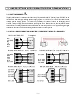
JUMPER SETTINGS & FIELD WIRING FOR SERIAL COMMUNICATIONS ......................... 3
4.
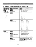
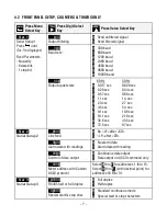
FRONT PANEL SETUP, SERIAL COMMUNICATIONS ...................................................... 6
5.
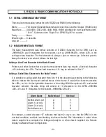
RS232 & RS485 COMMUNICATION PROTOCOLS ............................................................ 9
6.
CONTINOUS MODE ........................................................................................................... 11
7.
COMMAND MODE ............................................................................................................. 13
8.
APPENDIX A: DPM MEMORY ADDRESSES AND DATA DEFINITIONS .............................. 23
9.
APPENDIX B: COUNTER / TIMER MEMORY ADDRESSES AND DATA DEFINITIONS ........ 30
2. INTRODUCTION, CUSTOM ASCII SERIAL PROTOCOL
This manual applies
to our programmable digital panel meters, counters and timers with Series 2
firmware. Before applying this manual to your device, verify that the label states “Series 2.”
The Custom ASCII Protocol
is a simple serial communications protocol which is optimized for use
with Series 2 programmable digital panel meters, counters and timers. It is compatible with
RS232 and RS485 signals. It supports point-to-point and multipoint (or multidrop) communi-
cations, with addressing of up to 31 devices on the same RS485 serial data line.
Digital panel meters, counters and timers require a plug-in option board for serial communi-
cations. This can be an RS232 board, RS485 board, or RS485 Modbus board. The RS485 and
RS485 Modbus boards are electrically equivalent, but the RS485 board uses RJ11 connectors,
while the RS485 Modbus board uses RJ45 connectors. All of the serial board support the Modbus
protocol. The two RJ11 or RJ45 connectors are wired in parallel to allow daisy chaining with no
need for a hub. One of the jacks is equipped with two indicator LEDs.
The Modbus Protocol is a software-selectable alternative to the Custom ASCII Protocol and can be
used with RS232 or RS485 signal levels. It is an industry standard which allows devices by
different manufacturers to be digitally addressed on the same RS485 serial data line. However, it
is substantially more complex than the Custom ASCII Protocol. For additional information, please
refer to the separate Modbus Protocol Communications Manual.


