background image


12 

May 2015 

K0582 Revision B 

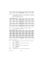
Bit 31–0 

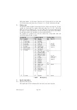
GAIN_ADJ [31..0]: Read/write – the value of this register is used to modify the 
value of the COMP_PRES register (address 1).  It is used in conjunction with the 

OFFSET_ADJ register (address 69) during user re-calibration of the sensor. 

 0x

n..n

 Number 

type 

float 


1.0 

Default 

value 


Address 69 – OFFSET_ADJ 

3.3.13

Bit 31 

Bit 30 

Bit 29 

Bit 28 

Bit 27 

Bit 26 

Bit 25 

Bit 24 

OFFSET _ADJ [31..24] 

R/W-X 

Bit 23 

Bit 22 

Bit 21 

Bit 20 

Bit 19 

Bit 18 

Bit 17 

Bit 16 

OFFSET _ADJ [23..16] 

R/W-X 

Bit 15 

Bit 14 

Bit 13 

Bit 12 

Bit 11 

Bit 10 

Bit 9 

Bit 8 

OFFSET _ADJ [15..8] 

R/W-X 

Bit 7 

Bit 6 

Bit 5 

Bit 4 

Bit 3 

Bit 2 

Bit 1 

Bit 0 

OFFSET _ADJ [7..0] 

R/W-X 

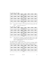
Bit 31–0 

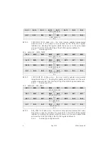
OFFSET_ADJ [31..0]: Read/write – the value of this register is used to modify 
the value of the COMP_PRES register (address 1).  It is used in conjunction with 
the GAIN_ADJ register (address 68) during user re-calibration of the sensor. 

 0x

n..n

 Number 

type 

float 


0.0 

Default 

value 


Address 70 – MAX_RANGE 

3.3.14

Bit 31 

Bit 30 

Bit 29 

Bit 28 

Bit 27 

Bit 26 

Bit 25 

Bit 24 

MAX_RANGE [31..24] 

R-X 

Bit 23 

Bit 22 

Bit 21 

Bit 20 

Bit 19 

Bit 18 

Bit 17 

Bit 16 

MAX_RANGE [23..16] 

R-X 

Bit 15 

Bit 14 

Bit 13 

Bit 12 

Bit 11 

Bit 10 

Bit 9 

Bit 8 

MAX_RANGE [15..8] 

R-X 

Bit 7 

Bit 6 

Bit 5 

Bit 4 

Bit 3 

Bit 2 

Bit 1 

Bit 0 

MAX_RANGE [7..0] 

R-X 

Bit 31–0 

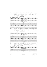
MAX_RANGE [31..0]: Read only – the upper limit of the sensor pressure range in 

the pressure units defined by the PRES_UNIT register (address 84). 

 0x

n..n

 Number 

type 

float 


Address 71 – MIN_RANGE 

3.3.15

Bit 31 

Bit 30 

Bit 29 

Bit 28 

Bit 27 

Bit 26 

Bit 25 

Bit 24 

MIN_RANGE [31..24] 

R-X 

Bit 23 

Bit 22 

Bit 21 

Bit 20 

Bit 19 

Bit 18 

Bit 17 

Bit 16 

MIN_RANGE [23..16] 

R-X 

Summary of Contents for BAKER HUGHES DPS 5000 Series

Page 1: ...GE Measurement Control DPS 5000 Series Sensors I2C bus Pressure Transducer User Manual K0582 English...

Page 2: ...Druck Ltd Fir Tree Lane Groby Leicester LE6 0FH UK Tel 44 0 116 231 7100 Fax 44 0 116 231 7103 2015 General Electric Company All rights reserved...

Page 3: ...ols to carry out required work on this sensor Pressure Do not apply pressure greater than the maximum safe working pressure to the sensor Toxic materials There are no known toxic materials used in the...

Page 4: ...nt bit byte mbar Millibar mH2O Metre of water mmHg Millimetre of Mercury mmH2O Millimetre of water MPa MegaPascal ms Millisecond MSB Most significant bit byte PCB Printed circuit board psi Pound per s...

Page 5: ...K0582 Revision B May 2015 iii References Reference 1 I2C bus specification and user manual NPX Semiconductor UM10204 Rev 6 available from www nxp com...

Page 6: ...ress 7 MVOLT_TEMP 10 3 3 9 Address 66 I2C_ADDR 10 3 3 10 Address 67 COEF_FIT 11 3 3 11 Address 68 GAIN_ADJ 11 3 3 12 Address 69 OFFSET_ADJ 12 3 3 13 Address 70 MAX_RANGE 12 3 3 14 Address 71 MIN_RANGE...

Page 7: ...emperature SNR 25 4 4 6 Maximising the update rate 26 4 4 7 Pressure re calibration 26 4 4 8 5 Maintenance 27 Cleaning 27 5 1 Adjustment 28 5 2 Repair 28 5 3 Disposal 28 5 4 Annex A Unit of pressure c...

Page 8: ...vi May 2015 K0582 Revision B Page left intentionally blank...

Page 9: ...ensors General view The DPS 5000 series sensors are low powered devices offering a high level of accuracy over a wide temperature range The I2C bus interface provides compensated pressure and temperat...

Page 10: ...o attain an acceptable temperature in systems where high pressures and high or low temperatures are present CAUTION The sensor contains ESD sensitive devices Whilst the sensor incorporates protection...

Page 11: ...s part of a network of compatible I2C bus devices CAUTION The DPS 5000 is intended for use within networks operated from a single supply at a voltage within the range 2 7 V to 3 6 V Operation outside...

Page 12: ...rd mode Supported 10 bit addressing Not supported Fast mode Not supported General call address Not supported Fast mode plus Not supported Clock stretching Supported High speed mode Not supported Softw...

Page 13: ...ata and coefficient data as shown in Table 3 Volatile data Configuration data Coefficient data Addr Register Addr Register Addr Register 0 STATUS 64 Reserved 128 Up to 30 pressure coefficient register...

Page 14: ...it 7 Bit 6 Bit 5 Bit 4 Bit 3 Bit 2 Bit 1 Bit 0 Reserved Reserved WRITE ADC_ON WENB VALID 1 0 CONV R 0 R 0 W 0 R X R 0 R X R X R W X Bit 31 16 Reserved read as 0 Bit 15 14 RESET 1 0 Write only performs...

Page 15: ...0 Not writable 0b1 Writable Bit 2 1 VALID 1 0 Read only used to indicate the status of the current values held in the COMP_PRES and COMP_TEMP registers addresses 1 and 2 Automatically cleared by readi...

Page 16: ...it 5 Bit 4 Bit 3 Bit 2 Bit 1 Bit 0 COMP_TEMP 7 0 R X Bit 31 0 COMP_TEMP 31 0 Read only the most recently updated compensated temperature value in C Reading this register whilst the sensor is in the au...

Page 17: ...address 0 0xn n Number type unsigned word Address 5 ACCESS 3 3 7 Bit 31 Bit 30 Bit 29 Bit 28 Bit 27 Bit 26 Bit 25 Bit 24 ACCESS 31 24 W 0 Bit 23 Bit 22 Bit 21 Bit 20 Bit 19 Bit 18 Bit 17 Bit 16 ACCESS...

Page 18: ...isters to calculate the values held in the COMP_PRES and COMP_TEMP registers addresses 1 and 2 Reading this register whilst the sensor is in the auto update mode will clear the CONV bit 0 flag of the...

Page 19: ...3 16 TP_FIT 7 0 Read only the number of pressure related temperature coefficients equal this value 1 0xn n Number type unsigned byte Bit 15 8 PT_FIT 7 0 Read only the number of temperature related pre...

Page 20: ...s register is used to modify the value of the COMP_PRES register address 1 It is used in conjunction with the GAIN_ADJ register address 68 during user re calibration of the sensor 0xn n Number type fl...

Page 21: ...d This value may be updated by the user following re calibration of the sensor 0xn n Number type unsigned integer5 Bit 15 8 MONTH 7 0 Read write the month in which the sensor was calibrated This value...

Page 22: ...0 bit 1 of the STATUS register address 0 will be cleared 0xn n Number type unsigned word Address 75 MAX_ADC_TEMP 3 3 19 Bit 31 Bit 30 Bit 29 Bit 28 Bit 27 Bit 26 Bit 25 Bit 24 MAX_ADC_TEMP 31 24 R X B...

Page 23: ...1 Bit 30 Bit 29 Bit 28 Bit 27 Bit 26 Bit 25 Bit 24 Reserved Reserved Reserved Reserved Reserved Reserved Reserved Reserved R 0 R 0 R 0 R 0 R 0 R 0 R 0 R 0 Bit 23 Bit 22 Bit 21 Bit 20 Bit 19 Bit 18 Bit...

Page 24: ...n Number type unsigned byte Bit 7 0 FIELD_4 7 0 Read only fourth software version field 0xn n Number type unsigned byte Address 82 AVERAGE 3 3 24 Bit 31 Bit 30 Bit 29 Bit 28 Bit 27 Bit 26 Bit 25 Bit 2...

Page 25: ...the value of this register is used to modify the value of the COMP_PRES register address 1 by the converting the value from the manufacturer s pressure units to the user pressure units 0xn n Number ty...

Page 26: ...X R W X R W X R W X R W X R W X R W X Bit 23 Bit 22 Bit 21 Bit 20 Bit 19 Bit 18 Bit 17 Bit 16 Unused Unused Unused Unused Unused Unused Unused Unused R W X R W X R W X R W X R W X R W X R W X R W X Bi...

Page 27: ...t 11 Bit 10 Bit 9 Bit 8 TARE_VALUE 15 8 R W X Bit 7 Bit 6 Bit 5 Bit 4 Bit 3 Bit 2 Bit 1 Bit 0 TARE_VALUE 7 0 R W X Bit 31 0 TARE_VALUE 31 0 Read write the value of this register is used to modify the...

Page 28: ...15 8 R W X Bit 7 Bit 6 Bit 5 Bit 4 Bit 3 Bit 2 Bit 1 Bit 0 KT IJ 7 0 R W X Bit 31 0 KT IJ 31 0 Read only 0xn n Number type float 4 Operational description Operational states 4 1 The basic operational...

Page 29: ...lculations Unless modified by the user see section 4 4 3 the unit of pressure is that used by the manufacturer during calibration of the sensor and defined in the PRES_UNIT register The unit of temper...

Page 30: ...difiable registers 4 4 1 The configuration data registers provide information for the user and allow the user to change the functionality of the sensor Table 4 lists the configuration data registers t...

Page 31: ...he configuration data registers as described in section 4 4 1 iv Reset the sensor Either power cycle the sensor or Write 0b10 to STATUS RESET 1 0 0 15 14 The sensor will now respond to the new I2C bus...

Page 32: ...actor from Annex A and update the pressure unit conversion factor value Write 14 50377 to PRES_CONV PRES_CONV 31 0 83 31 0 iii Save the new pressure unit conversion factor value to non volatile memory...

Page 33: ...a high SNR However for very low noise applications the user can modify the contents of the AVERAGE register to increase the SNR of either or both readings at the expense of the sensor acquisition time...

Page 34: ...set and may result in invalid pressure and temperature data Maximising the update rate 4 4 7 For applications that require the DPS 5000 sensor acquisition time to be faster than is achievable by adju...

Page 35: ...a registers as described in section 4 4 1 The user may also record the date of re calibration by modifying the date fields of CAL_DATE register For example to change the calibration date to 16th April...

Page 36: ...accuracy of at least 0 01 of reading Note GE can provide a calibration service that is traceable to international standards Repair 5 3 The DPS 5000 sensors contain no user serviceable items For any r...

Reviews: