6
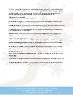
LOGIC CONNECTOR ASSIGNMENTS
Connector terminals 6 through 12 are used for command inputs in the Step Motor Drive mode. Terminals 7, 8 and 9 are
common cathode opto-isolated inputs with 200 Ohm current limit resistors. The inputs work with 2.5V, 3.3V and 5V logic levels.
Logic 1 input current is 2 mA. The output is an open collector opto-isolator that has a 10 mA current sink rating.
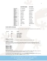
Terminal
Function
I/O
7
DISABLE IN
INPUT
8
DIRECTION
INPUT
9
STEP
INPUT
10
COMMON
EXTERNAL GROUND
11
FAULT OUT
OUTPUT
12
N/C
TERMINAL 7: DISABLE IN
The motor drive is ENABLED when this input is unused or has a logic 0 applied. The motor drive is DISABLED when this input has
a logic 1 (+5V) applied. When DISABLED, the motor current goes to zero, there is no switching activity on the motor outputs and
the motor free-wheels (detent torque). The motor position is restored if no step pulses have been sent while disabled.
TERMINAL 8: DIRECTION
The state of this input determines the direction a motor will move when a step pulse is received. The DIRECTION logic level must
be stable 250ns before the active edge of the step pulse.
TERMINAL 9: STEP
A positive edge on this input (logic 0 to logic 1) causes the motor to move one increment of motion. The minimum logic 1 time
is 1 microsecond and the minimum logic 0 time is 3 microseconds.
TERMINAL 10: COMMON
This is the ground terminal for the DISABLE, DIRECTION and STEP inputs and the FAULT output. It must go to the ground
terminal of the controller that generates these inputs.
TERMINAL 11: FAULT OUT
This output goes to a logic 1 when the drive goes into protective shutdown because of over-voltage, over-current or over-
temperature. Once the cause for the FAULT is corrected, the FAULT output can be cleared by cycling the power supply or the
DISABLE input. The FAULT LED blink code is below:
BLINK CODE
STATE INDICATED
Solid Green
Step and Direction Mode:
Power is applied.
VCO Mode:
Power applied and speed is set to zero.
Solid Red
Step and Direction Mode:
Drive is disabled, motor is
freewheeling.
GREEN-GREEN-GREEN-OFF
VCO Mode:
Motor rotation is CW
RED-RED-RED-OFF
VCO Mode:
Motor rotation is CCW
Table 1
When finished with the switch setup and wiring, it is OK to turn on power supply.
END OF G216 STEP MOTOR DRIVE MANUAL


