User Manual 07500524
Model 3000-524
Page 14
O
peration Manual
Chapter 7
Register Map
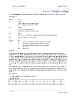
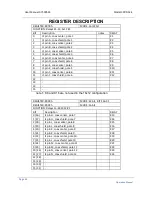
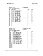
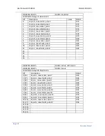
The following register map shows the signal name and register assignments for the Model 3000-524.
A16 Registers
Offset
Value
00h
7FB5h
7 = Register Based, A16/A24 Module
FB5 = VXI Manufacturer ID, ASCOR
02h
7xxxh
7 = A24 space requirement
xxx = Model Number for this module
04h
FFFCh
Bit 0, reset, is supported. Toggling this bit will clear all relay registers.
06h
(assigned by Resource Manager)
Control
Bit
3Eh
0
Low true output enable to the relay coil driver IC's.
1
When low enables read back of relay coil state
When high enables read back of data registers
2
Reserved
3-15
Don't Care
Programming
The Model 3000-524 is a VXI register based module. The switch paths are controlled via
VXIMAX
TM
which is the 16/32 bit data controller. The Model 3000-524 can be programmed in
16 bit or 32 bit wide data. Through your VXI controller, write the data to the appropriate register
as shown on the register map for the relay or relays in the register that is being closed. When
the data bit is true, the relay chosen will be closed. The state of the relays in a register can be
determined by reading the desired register. The data read back represents the value at the coil
of the relay. This allows verification that the program register has correctly controlled the relay
coil.
The following register maps are shown in two configurations: 16 bit mode and 32 bit mode. In
each section,16 bit and 32 bit, the register map is organized to show the relay designation in
each register. It is followed by the register’s functionality and the path connections to the front
panel.
For example:
To close relay K1 set the register bit 0 to a "1."
Register 8000h:
15
14
13
12
11
10
9
8
7
6
5
4
3
2
1
0
0
0
0
0
0
0
0
0
0
0
0
0
0
0
0
1


