

User Manual
GD32350R-EVAL
21 /33
5.7.2.
DEMO Running Result
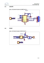
Jump the JP12 to RS485 and JP13 to USART with the jumper cap. This routines need
to prepare two GD32F350R_EVAL boards, one board as a sender, the other as a
receiver. First connect two GD32350R-EVAL boards through RS485 line A and B, and
then download the program < 07_RS485_Test > to the board for running.
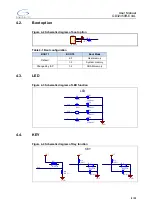
When press
the Wakeup key on one board, the board is set as RS485 transmitter and LED2 is on
and when press the Tamper key on one board, the board is set as RS485 receiver and
LED3 is on.
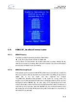
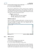
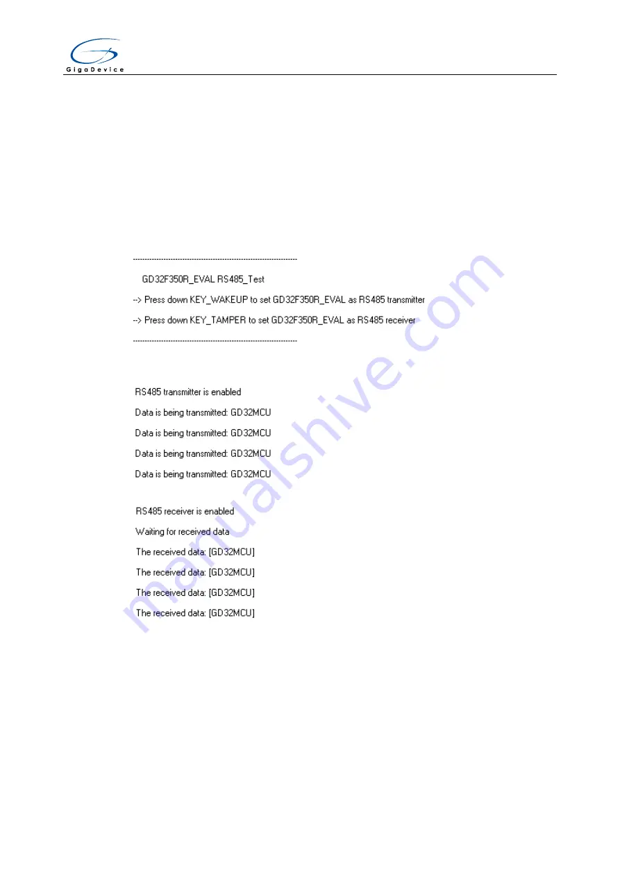
Download the program < 07_RS485_Test > to the EVAL board and run,
the information
via a serial port output as following:
According to the tips, press down Wakeup key to set one board as a transmitter and
press down Tamper key to the other as a receiver. The transmitter output as following.
The receiver output as following.
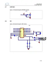
5.8.
ADC_Conversion_Triggered_By_Timer
5.8.1.
DEMO Purpose
This Demo includes the following functions of GD32 MCU:
Learn to use ADC to convert analog to digital
Learn to use TIMER to generate a CC event


