Document Version 1.2
Last revised on
2017-09-26
Page 76 of 92
Reference Manual for uTrust 4701F and uTrust 4711F Readers
6.3.5.1.
CONTACT_GET_SET_PWR_UP_SEQUENCE
This Escape command is used to get or set the following parameters:
●
Smart card Power-on sequence
●
Delay between successive Activation retires
●
Enable/Disable any Voltage Class
As soon as card insertion is detected and Power ON message is received from the host, the firmware
will start Activation with the configured voltage sequence. If the Activation fails, it will wait for the
configured Activation delay and then retry with the next enabled Voltage class. If power up succeeds
at an operating voltage, the firmware will continue card communication at that voltage. If power up
fails in all the enabled operating voltages, then the firmware will report an error.
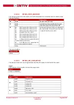
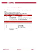
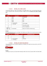
Input:
The first byte of the input buffer will contain the escape code. The next byte shall contain the function
to be performed. Third byte shall contain the parameter for the function.
Byte0
Byte1
Byte2
Value Description
Escape code(0x04)
0x00
Starts with Class C voltage.
(1.8V – 3V – 5V order)
-
0x01
Starts with Class A voltage. (5V
– 3V – 1.8V order)
-
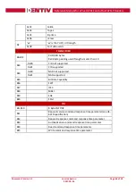
0x08
Time delay between resets
Delay value in milliseconds
0x09
Enable/Disable a Voltage Class
Bit Map of all Voltage Classes
[Bit0 – Class A; Bit1 – Class B;
Bit2 – Class C]
Set bit to enable the Voltage
class
Clear bit to disable the Voltage
class
0xFE
Retrieves all the Activation
Configuration
-
0xFF
Retrieves the current Power
up sequence
-

