Document Version 1.2
Last revised on
2017-09-26
Page 77 of 92
Reference Manual for uTrust 4701F and uTrust 4711F Readers
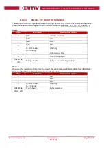
Output:
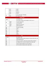
For retrieving all settings (0xFE), the output will be:
Byte0
Value
Description
Byte 1
Byte2
0x00
Starts with Class C voltage.
(1.8V – 3V – 5V order)
Time delay between
resets in milliseconds
Bit Map of all Voltage
Classes
[Bit0 – Class A; Bit1 –
Class B; Bit2 – Class C]
0x01
Starts with Class A voltage.
(5V – 3V – 1.8V order)
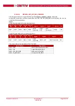
For retrieving current Power up sequence (0xFF), the output will be:
Byte0 Value
Description
0x00
Starts with Class C voltage. (1.8V – 3V – 5V order)
0x01
Starts with Class A voltage. (5V – 3V – 1.8V order)
Example: retrieve all the current settings:
DataIn =
04 FE
DataOut:
01 0A 07
(3 bytes)
00:
Starting with Class A
0A:
10ms delay between resets
07:
Class A, B, and C enabled
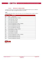
6.3.5.2.
CONTACT_EMV_LOOPBACK
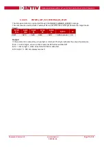
This Escape command lets the host force the firmware to perform an EMV Loop-back application.
Input:
The input buffer contains the escape code value.
Byte0
Escape code(0x05)
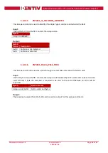
Output:
Output buffer
NULL

