4. DMA
114
PowerSpan II User Manual
80A1010_MA001_09
Integrated Device Technology
www.idt.com
4.2
DMA Register Description
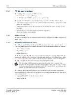
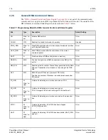
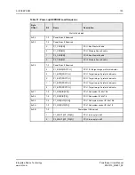
The DMA registers are the same for each DMA channel. DMA registers are described in
. The
registers for DMA1 begin at offset 0x300 and their organization in PowerSpan II register space is
described in
“Register Descriptions” on page 235
.
4.2.1
Source and Destination Addresses
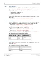
The lower three bits of DMA Destination Address register are taken directly from the lower three bits
of the Source Address register. This enforces 8-byte alignment of the starting source and destination
addresses. The source and destination address registers are part of the command packet contents
(
“Linked-List Mode DMA Operation” on page 120
).
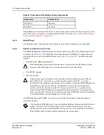
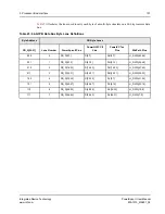
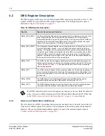
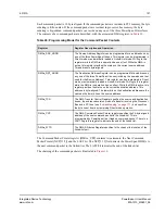
Table 26: DMA Register Description
Register
Register Description and Operation
DMAx_SRC_ADDR
The Source Address Register can be programmed for an address on any one of the
three PowerSpan II buses. This register can be programmed in Direct mode or
automatically loaded in Linked-List mode. Writing to this register while the DMA is in
operation has no effect. While the DMA is active, this register provides the current
status of the source address. This address is byte-aligned.
DMAx_DST_ADDR
The Destination Address Register can be programmed for an address on any one of
the three PowerSpan II buses
—
even the same bus as that used for the Source
Address. This register can be programmed in Direct mode or automatically loaded in
Linked-List mode. Writing to this register while the DMA is in operation has no effect.
While the DMA is active, this register provides the status of the current destination
address. This address is byte-aligned. The lower bits on the destination address are
the same as the lower bits on the source address.
DMAx_TCR
The DMA Transfer Control Register specifies the source and destination buses, the
endian conversion mode of a transfer involving the processor bus and a PCI bus (see
), and specifies the byte count from any remaining
Direct mode operation.
DMAx_CPP
The DMA Command Packet Pointer register specifies the 32-byte aligned address of
the next command packet in the linked-list. This is programmed by PowerSpan II as it
loads a command packet. There is a LAST flag in this register to indicate the end of
the linked-list.
DMAx_GCSR
The DMA General Control and Status Register controls DMA activity, reflects
operational status and enables DMA-specific interrupts (see
DMAx_ATTR
The DMA Attributes Register controls the transfer type and cache-specific behavior
of processor bus transactions. It also selects the command packet port.
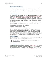
Most DMA channel registers are locked against any changes by the user while the channel is
active. However, both the Stop Request (STOP_REQ) and Halt Request (HALT_REQ) bits,
in the
“DMA x General Control and Status Register” on page 314
, are not locked.

