background image

80 

Basic System Management 

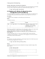
10.7  Display Time since last Restart 

Procedure 

To display the time since last restart 

Mode 

Operator execution 


 Command 

Purpose 

Step 1 

node

>show uptime 

Display the time since last restart. 

Example:  

The following example shows how to display the uptime of your device, if you start from the 
configuration mode. 
 

SN>

show uptime


The system is up for 1 days, 23 hours, 44 minutes, 18 seconds 

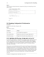
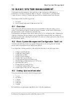
10.8  Configuring and Starting the Web Server 

SmartNode includes an embedded web server, which can be used together with a customer-specific 
Java applet that must be downloaded into the persistent memory region of your SmartNode. Applets 
are similar to applications but they do not run as standalones. Instead, applets adhere to a set of 
conventions that lets them run within a Java-compatible browser. With a Java applet, custom-specific 
configuration tasks of SmartWare are possible using a browser instead of accessing the SmartWare 
CLI via Telnet or the serial console. 
 
Without a Java applet the value of the embedded web server is limited. Contact Inalp Networks for 
any questions about custom designed Java configuration tools for SmartWare. 
 

Procedure 

To set the webserver language and the listening port. 

Mode 

Configure 


 Command 

Purpose 

Step 1 

node

(cfg)#webserver lang {

de


en

Sets the language to either German (de) or English 
(en) 

Step 3  

node

(cfg)#webserver port 

number 

Sets the listening port number in the 1 to 65535, 
default port number for web server is 80 

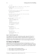
Example: Configuring and Starting the Web Server 

The following example shows how to set the webserver language and the listening port of your 
device, if you start from the configuration mode. 
 

SN(cfg)#

webserver lang en


SN(cfg)#

webserver port 80


Software Configuration Guide, Revision 1.03 

Summary of Contents for SmartWare R2.00

Page 1: ...Software Configuration Guide SmartWare Release 2 00 Customer Deliverable Documentation Part Number 80 0123 English Revision 1 03 March 14 2002 ...

Page 2: ......

Page 3: ...istered trademarks of Inalp Networks AG SmartWare and SmartView are trademarks of Inalp Networks AG All other trademarks mentioned in this document are property of their respective owners EU Declaration of Conformity The EU Directives covered by this Declaration 89 336 EEC Electromagnetic Compatibility Directive amended by 92 31 EEC 93 68 EEC 72 23 EEC Low Voltage Equipment Directive amended by 93...

Page 4: ... 4 Profiles and Use commands 32 4 4 1 Profiles 32 4 4 2 Use Commands 32 5 Command Line Interface 33 5 1 Command Modes 33 5 1 1 System Prompt 34 5 1 2 Navigating the CLI 35 5 2 Command Editing 37 5 2 1 Command Help 37 5 2 2 The No Form 37 5 2 3 Command Completion 37 5 2 4 Command History 37 5 2 5 Command Editing Shortcuts 37 6 Accessing the SmartWare Command Line Interface 40 6 1 Introduction 40 6 ...

Page 5: ...twork Server to Flash Memory 61 8 9 Copy Driver Software from a Network Server to Flash Memory 62 9 Configuration File Handling 64 9 1 Introduction 64 9 1 1 Understanding Configuration Files 65 9 2 Factory Configuration 66 9 3 Warnings 67 9 4 Configuration File Handling Task List 67 9 5 Copy Configurations within the Local Memory 67 9 6 Replacing the Startup Configuration with a Configuration from...

Page 6: ...edirect Messages 94 12 8 Router Advertisement Broadcast Message 94 12 9 Defining the MTU of the Interface 95 12 10 Configuring an Interface as a Point to Point Link 96 12 11 Displaying IP Interface Information 96 12 12 Testing Connections with the ping Command 97 12 13 Examples 98 12 13 1 Deleting an IP Interface Example 98 13 NAPT Configuration 99 13 1 Overview 99 13 2 Configuring Network Address...

Page 7: ... 15 8 8 Specifying Layer 2 Marking 127 15 8 9 Defining Random Early Detection 128 15 8 10 Discarding Excess Load 128 15 9 Devoting the Service Policy Profile to an Interface 129 15 10 Displaying Link Arbitration Status 130 15 11 Displaying Link Scheduling Profile Information 131 15 12 Enable Statistics Gathering 131 16 Serial Port Configuration 133 16 1 Introduction 133 16 2 Serial Port Configurat...

Page 8: ...n 162 19 1 About Access Control Lists 162 19 1 1 What Access Lists Do 162 19 1 2 Why You Should Configure Access Lists 162 19 1 3 When to Configure Access Lists 163 19 1 4 Features of Access Control Lists 163 19 2 Access Control List Configuration Task List 164 19 3 Map Out the Goals of the Access Control List 164 19 4 Create an Access Control List Profile and Enter Configuration Mode 165 19 5 Add...

Page 9: ...22 6 Configure Session Routing Tables 209 22 6 1 Broadcast Handling in the Session Router 209 22 6 2 Configure Number Prefix for ISDN Number Types 209 22 6 3 Create a Called Party Number Routing Table 210 22 6 4 Create a Calling Party Number Routing Table 211 22 6 5 Create a Bearer Capability Routing Table 212 22 6 6 Create a Time of Day Routing Table 213 22 6 7 Create a Day of Week Routing Table ...

Page 10: ...5 7 Examples 247 25 7 1 Branch Offices in an Enterprise Network 247 25 7 2 Gatekeeper in LAN Based Telephony 249 26 VoIP Profile Configuration 251 26 1 Introduction 251 26 2 VoIP Profile Configuration Task List 252 26 3 Create a VoIP Profile 252 26 4 Enable DTMF Relay 253 26 5 Enable Echo Canceller 254 26 6 Enable Silence Compression 255 26 7 Configure Voice Volume 256 26 8 Configure Dejitter Buff...

Page 11: ...289 29 4 Defining SNTP Client Operating Mode 290 29 5 Defining SNTP Local UDP Port 291 29 6 Enabling and Disabling the SNTP Client 291 29 7 Defining SNTP Client Poll Interval 292 29 8 Defining SNTP Client Constant Offset To GMT 292 29 9 Defining the SNTP Client Anycast Address 293 29 10 Enabling and Disabling Local Clock Offset Compensation 294 29 11 Enabling and Disabling Root Delay Compensation ...

Page 12: ...perience but who might not be familiar with the SmartNode System administrators who are responsible for installing and configuring networking equipment and who are familiar with the SmartNode Document Conventions Inalp documentation uses the conventions listed in the Table 1 1 through Table 1 3 below to express instructions and information Notice Description Note Helpful suggestions or references ...

Page 13: ...iption How to Read this Guide SmartWare is a complex and multifaceted operating system running on your SmartNode Without the necessary theoretical background you will not be able to understand and consequently use all the features available Therefore we recommend reading at least the chapters listed below to get a general idea about SmartWare and the philosophy of contexts used for IP and circuit ...

Page 14: ...ecific architecture are included here 1 2 SmartWare Architecture Terms and Definitions In Table 1 1 terms or definitions used to describe the SmartWare architecture are alphabetically sorted Term or Definiton Meaning Administrator The person who has priviledged access to the SmartWare CLI Application Download A application image is downloaded from a remote TFTP server to the persistent memory flas...

Page 15: ...cupy 64 kbps using PCM pulse code modulation coding Over the years compression techniques were developed allowing a reduction in the required bandwidth while preserving voice quality Such compression techniques are implemented witin a Codec Comfort Noise Comfort noise is generated at the remote end of the silent direction to avoid the impression that the connection is dead See also Silence Compres...

Page 16: ...ored in the persistent memory flash of a SmartNode DTMF Relay DTMF relay solves the problem of DTMF distortion by transporting DTMF tones over low bit rate codecs out of band or separate from the encoded voice stream Echo Canceller Some voice devices unfortunately have got an echo on their wire Echo cancelation provides near end echo compensation for this device Factory Configuration The factory c...

Page 17: ...tation whereas node generally applies to any networked system including access servers and routers See also node Hostname Name given to a computer system e g a PC or workstation Hunt Group In the SmartNode terminology a hunt groups allows you to apply the interface configuration to multiple physical ports Within the hunt groups free channels for outgoing calls are hunted on all available ports In ...

Page 18: ...d configurations Operator The person who has limited access to the SmartWare CLI PCI Local Bus The PCI Local Bus is a high performance 32 bit or 64 bit bus with multiplexed address and data lines The bus is intended for use as an interconnect mechanism between highly integrated peripheral controller components peripheral add in boards and processor memory systems PCM Highway A 30 channel interface...

Page 19: ...comprise additional services for the Private ISDN network such as CNIP Calling Name Identification Presentation CNIR Calling Name Identification Restriction etc See also ISDN Services Release SmartWare is organized in releases that define the main voice and data features of a SmartNode Several builds can be available from ca ertain release See also build Routing Engine In SmartWare the routing eng...

Page 20: ...rtWare is available in several releases that in general support all currently available SmartNode models Startup Configuration The startup configuration is stored in the persistent memory nvram and is always copied for execution to the running configuration in the volatile memory system after a system start up Switching Engine Part of the SmartNode hardware which allows software controlled circuit...

Page 21: ...ing These applications are also called Multiservice Intranets MSI 3 Applications in LAN telephony in which the SmartNodes serve as gateways between the LAN and the local PBX or PSTN access These applications are also called LAN voice gateway LVG 2 2 Carrier Networks The network termination NT device in a multi service IP based provider network plays a vital role It provides the service access poin...

Page 22: ... interconnection Typical access technologies for these networks include xDSL WLL PowerLine and conventional leased lines With the use on an external modem M the SmartNode can connect to leased lines or any bridged Ethernet broadband access 2 3 Enterprise Networks In company owned and operated wide are networks SmartNodes can be used to converge voice and data communications on the same IP link In ...

Page 23: ...s a standalone gateway for H 323 LAN voice systems such as LAN based PBXs or call centers A standalone gateway has performance reliability and scalability advantages compared with PC based gateway cards In this application the SmartNode also offers a migration path to enterprise or carrier networking Figure 2 3 shows the deployment of a SmartNode as a LAN voice gateway The PSTN connections can be ...

Page 24: ...24 Applications Figure 2 3 Typical LAN Telephony System Software Configuration Guide Revision 1 03 ...

Page 25: ...ed software running on the SmartNode hardware platforms The software designed by Inalp Networks AG for the SmartNodes is termed SmartWare This software is handled as a separate element because it is as far as possible platform independent and so provides the same features and functionality throughout the complete SmartNode model range The third element is the set of SmartView management tools prov...

Page 26: ...ystem model of an Inalp SmartNode is depicted in Figure 3 2 Both the SmartNode 1000 and the 2000 series have three main components 64k circuit switching is supported between on board ISDN ports and on and between ISDN and PSTN interface cards The circuit switching engine uses dedicated hardware resources and therefore can bypass the VoIP gateway and packet routing engine Gateway GW which converts ...

Page 27: ...ected download files to improve download efficiency and security The download to the SmartNode is handled in sequence using a download batchfile Refer to Chapter 8 System Image Handling for details on SmartWare image downloads In addition to the actual SmartWare images there are several additional embedded software components that you will encounter The boot loader is a mini application that perfo...

Page 28: ...ne Interface CLI which supports full online configuration and monitoring access for the operator The SNMP agent and MIB with an emphasis on inventory and alarm management for integration in a 3rd party Network Management System NMS With the aid of configuration files and TFTP up and downloads the SmartNodes can also be managed offline using standard text editors and file systems A number of host b...

Page 29: ...s 4 1 Introduction and Overview The Inalp SmartNodes are multi service network devices that offer high flexibility for the inter working of circuit switched and packet routed networks and services In order to consistently support a growing set of functions protocols and applications SmartWare configuration is based on a number of abstract concepts that represent the various SmartWare components Fi...

Page 30: ...uration of all SmartNodes Note SmartWare currently supports only one instance of the CS and IP context types Examples The IP context named router can contain static routes RIP and NAT configuration parameters The circuit switching context named switch can contain number translations local breakout conditions and least cost routing parameters 4 2 2 Gateway For the communication between contexts of ...

Page 31: ...ng concept Examples of SmartNode ports are 10bT Ethernet Serial ISDN BRI and ISDN PRI Ports are numbered according to the SmartNode port numbering scheme The port name corresponds to the label or abbreviation printed on the hardware Example Ethernet 0 1 Serial 0 0 BRI 3 2 Some ports may contain multiple circuits For example serial ports can contain one or more Frame Relay Permanent Virtual Circuit...

Page 32: ...ions of groups of configuration commands that are the same for multiple elements in a configuration Figure 4 1 shows profiles that are used in the IP and CS contexts 4 4 2 Use Commands Use commands form the association between profiles and contexts gateways or interfaces For example when a profile is used in a context all the configuration settings in that profile become active within the context ...

Page 33: ...rmation on command syntax and usage guidelines for each CLI command refer to Chapter 1 Command Line Interface in the SmartWare Command Reference Guide 5 1 Command Modes The CLI is comprised of modes There are two mode groups the exec mode group and the configuration mode group Within the exec mode group there are two modes operator exec and administrator exec The configuration mode group contains ...

Page 34: ...d Line Interface Figure 5 1 Command Line Modes 5 1 1 System Prompt For interactive on line sessions the system prompt is of the form nodename In the operator exec mode Software Configuration Guide Revision 1 03 ...

Page 35: ...he system using a subset of the available CLI commands System Changes In order to make any changes to the system the administrator exec privileged exec mode must be entered The enable user interface command is used for this purpose Once in administrator exec mode all of the system commands are available to you The enable command is only accessible if you are logged in as an administrator Configura...

Page 36: ...context cs config mode node if_isoip name interface_h323 interface h323 name command from context cs config mode nod if h323 name gateway_isoip gateway isoip isoip command from configure mode node gw isoip isoip gateway_h323 gateway h323 h323 command from configure mode node gw h323 h323 port_ethernet port ethernet slot port command from configure mode node prt eth slot port port_serial port seria...

Page 37: ...e tool enter the command debug session router To subsequently disable the Session Router trace enter the command no debug session router 5 2 3 Command Completion You can use the Tab key in any mode to carry out command completion Partially typing a command name and pressing the Tab key causes the command to be displayed in full up to the point where a further choice has to be made For example rath...

Page 38: ...38 Command Line Interface Esc f is handled differently press and release the Escape key often labeled Esc on many keyboards and then press the f key Software Configuration Guide Revision 1 03 ...

Page 39: ...Move cursor backward one character Esc f Move cursor forward one word Esc b Move cursor backward one word Ctrl a Move cursor to beginning of line Ctrl e Move cursor to end of line Ctrl k Delete to end of line Ctrl u Delete to beginning of line Ctrl d Delete character Esc d Delete word Ctrl c Quit editing the current line Ctrl l Refresh redraw the display Ctrl t Transpose characters Table 5 2 Comma...

Page 40: ...de model in the SmartNode Hardware Configuration Guide Remember that the CLI supports a command history and command completion By scrolling with the Up and Down Arrow keys you can find many of your previously entered commands Another timesaving tool is command completion If you type part of a command and then press the Tab key the SmartWare shell will present you with either the remaining portion ...

Page 41: ... Setup For Initial Configuration via the Console Port 6 4 1 Console Port Procedure Before you begin to use the CLI to enter configuration commands carry out these five steps Step 1 Set up the hardware as described in the Hardware Installation Guide Step 2 Configure your serial terminal for 9600 baud 8 data bits no parity 1 start bit 1 stop bit and no flow control Step 3 Connect the serial terminal...

Page 42: ...onfigured you must use the console interface Figure 6 2 Setup For Initial Configuration via an Ethernet Port The host must have a valid IP address configured in the same subnet as the SmartNode Table 6 1 shows the default IP address and netmask of the Ethernet ports of the SmartNode Port IP Address Network Mask ETH 0 10 0 0 10 255 255 0 0 16 ETH 1 10 1 0 10 255 255 0 0 16 Table 6 1 Default IP Addr...

Page 43: ... your SmartNode via the local console port or via a Telnet session will open a login screen The following description of the login process is based on a Telnet session scenario but is identical when accessing via the local console port The opening Telnet screen is depicted in Figure 6 3 The window header bar shows the IP address of the target SmartNode At the very beginning a factory preset admini...

Page 44: ...How am I going to remember that It s easy the password above is an acronym taken from 3 blind mice see how they run Making a good password is that easy But please don t use the above example password for your SmartNode device 6 8 Configure Operators and Administrators To secure the system as well as to enable remote access to the system you must create operator and administrator login accounts The...

Page 45: ...SmartNode is saved so that it will be used following a reload Example Create an Operator Account The following example shows the commands used to add a new operator account with a login name support and a matching password of s4DF qw The changed configuration is then saved SN enable SN configure SN cfg operator support password s4DF qw SN cfg copy running config startup config 6 11 Create an Admin...

Page 46: ...rocedure To display the version of the currently running SmartWare CLI Mode Operator execution Command Purpose Step 1 node show version cli Displays CLI version Example Displaying the CLI Version The following example shows how to display the version of the current running SmartWare CLI on your device if you start from the operator execution mode SN show version cli CLI version 2 00 6 13 Display A...

Page 47: ...to Another Account The following example shows how to change from your current user account to an administrator account starting from operator execution mode In the example below the who command is used to check the identity within both accounts login support password password SN who You are operator support SN su super Enter password password SN who You are administrator super 6 15 Checking Ident...

Page 48: ...of the user executing the who command ID represents the ID of the account State represents the actual running condition of the user which can be logout login exec and config Used in operator execution mode SN who You are operator support 6 16 End a Telnet or Console Port Session To end a Telnet or console port session you use the logout command in the operator or administration execution mode To c...

Page 49: ...he Telnet session to the SmartNode is terminated and the Telnet application window on your host closes Note Using the command exit in the operator execution mode also terminates a Telnet or console port session but without any confirmation dialog Software Configuration Guide Revision 1 03 ...

Page 50: ...stablish network based IP connectivity to and from your SmartNode 7 2 IP Context Selection and Basic Interface Configuration Tasks The basic tasks involved in configuring an IP context the related interfaces and ports are Enter the IP Context Create IP Interfaces and Assign an IP Address Define IP Ethernet Encapsulation and Bind IP Interface to a Physical Port Activate the Physical Port Display IP...

Page 51: ...an IP interface is accessible the IP Ethernet encapsulation has to be defined for the related port It is assumed that you would like to define IP Ethernet encapsulation for port port on slot slot Before an IP interface can be used it needs to be bound to a physical port of your SmartNode The SmartNode has one or more expansion slots that can have one or more ports Specifying a port unambiguously m...

Page 52: ...n slot 0 which is in the shutdown state as indicated by CLOSED for the current state SN prt eth 0 1 show port ethernet 0 0 Ethernet Configuration Port ethernet 0 0 0 State CLOSED MAC Address 00 30 2B 00 1D D4 Speed 10MBit s Duplex Half Encapsulation ip Binding wan router Frame Format standard Default Service 0 To activate a port for operation the shutdown status of the port has to be removed That ...

Page 53: ...the show ip interface command can be longer SN ctx ip router show ip interface Context router Name lan IP Address 192 168 1 3 255 255 255 0 P2P point to point MTU 1500 ICMP router discovery enabled ICMP redirect send only State OPENED Binding ethernet 0 0 0 ethernet ip An easy way to list existing interfaces is by using the interface command followed by a in the IP context configuration mode which...

Page 54: ...s named external with the no interface command with the interface name as argument SN ctx ip router no interface external Finally list the interfaces again to check if the IP interface external has been deleted SN ctx ip router interface interface New interface internal Existing interface lan Existing interface wan Existing interface 7 8 Examples 7 8 1 Setting Up an IP Interface on an Ethernet Por...

Page 55: ...he Ethernet port 0 on slot 0 is selected the medium is set to 10 Mbit s in half duplex mode and IP encapsulation for this port is chosen SN if ip lan port ethernet 0 0 SN prt eth 0 0 medium 10 half SN prt eth 0 0 encapsulation ip Afterwards the just defined interface lan is bound to the Ethernet port and then the port is activated SN prt eth 0 0 bind interface lan router SN prt eth 0 0 no shutdown...

Page 56: ...wn operational configuration files are stored in the SmartNode flash memory and copies may also be stored on a remote server Transferring configuration files between the flash memory and a remote server requires the use of the Trivial File Transfer Protocol TFTP The TFTP server must be accessible through one of the SmartNode IP interfaces TFTP is not possible over the console interface In the foll...

Page 57: ...ical region nvram can be copied to a remote server using TFTP Since configurations are not executable from persistent memory any configuration that is to be used has to be copied into the volatile memory of the SmartNode prior to operation This procedure takes place after the system bootstrap where the application image i e SmartWare is started and a configuration must be available Shortly before ...

Page 58: ...l region nvram for an application image Following that the application image is executed that is SmartWare is started module by module Shortly before SmartWare is fully started up the configuration startup config is copied from the logical region nvram of flash memory as running config into the volatile memory system and is used to parameterize SmartWare Figure 8 2 illustrates the boot procedure S...

Page 59: ...age if the download was not successful If the application image is valid it is started and SmartWare is brought into operation module by module During this system initialization phase the status of the Reset button on the back plane of the SmartNode is checked If the button has been pressed the factory configuration is loaded into the volatile memory and is used to parameterize SmartWare If the bu...

Page 60: ...ormation Copy System Images from a Network Server to Flash Memory Copy driver software from a Network Server to Flash Memory 8 7 Display System Image Information Procedure To display information about system images and driver software Mode Administrator execution Command Purpose show version Lists the system software release version information about optional interface cards mounted in slots and o...

Page 61: ... not be needed Downloading a new system image file means storing it permanently at a defined location within the SmartNode flash memory To store the system image file a special download script file has to be used This script file defines how the system image file is to be handled and where it is to be stored You cannot download any system image file without an appropriate script file Each line in ...

Page 62: ...1 node cfg copy tftp node ip adress b flash Downloads the script file b from the TFTP server at address node ip address and starts the system image download process This progress is visualized with a counter counting up from 0 to 100 according to the downloaded amount of the file size for each file that needs to be downloaded Example Copy System Images from a Network Server to Flash Memory The fol...

Page 63: ...rocedure To download a driver software image file Mode Administrator execution Command Purpose Step 1 node cfg copy tftp node ip adress b flash Downloads the script file b from the TFTP server at address node ip address and starts the driver software image download process This progress is visualized with a counter counting up from 0 to 100 according to the downloaded amount of the file size for e...

Page 64: ... is defined as the startup configuration Changing the current running configuration is possible as follows You may change the running configuration interactively Interactive configuring requires that you access the CLI using the enable command to enter administrator execution mode Then you must switch to the configuration mode by typing the command configure Once in configuration mode you can ente...

Page 65: ...on files For better comprehension SmartWare allows comments within configuration files To add a line with a comment to your configuration file simply begin the line with the hash character The command parser skips everything after the hash character to the end of the line SmartNode IP and Voice configuration Node SN Config SN2300_001 cfg Model SN2300 0001 0001 Serial No 100000021579 Administrator ...

Page 66: ...h configuration file that is stored in the flash memory needs a unique name The user has to assign a file name to any user specific configuration SmartWare predefines some names for configuration files These are the file names used to represent the factory configuration startup configuration and running configuration which are factory config startup config and running config Refer back to Chapter ...

Page 67: ... display copy delete and down or upload configuration files perform the tasks described in the following sections Copy Configurations within the Local Memory Replacing the Startup Configuration with a Configuration from Flash Memory Copy Configurations to and from a Remote Storing Location Replacing the Startup Configuration with a Configuration downloaded from TFTP Server Displaying Configuration...

Page 68: ...ut replicates a selected source to a target configuration file in the specified memory region Therefore the source configuration file is not lost after the copy process There are three predefined configuration files names for which the specification of the memory region is optional namely the files factory config startup config and running config Procedure To copy a specified configuration with an...

Page 69: ...ng persistent startup configuration with the startup configuration new startup already present in flash memory Note It is assumed that the configuration new startup that is present in flash memory was previously copied to the flash memory e g from a TFTP server using the copy command Example Replacing the Startup Configuration with a Configuration from Flash Memory The following example shows how ...

Page 70: ... name and path of the configuration file We will explain the usage of the remote memory region tftp in the following section more detailed Another typical task is uploading the current running configuration to the remote data store for backup purpose or if an extensive configuration file is to be edited on the remote host In this case the running configuration named running config which is to be f...

Page 71: ...by downloading a configuration from the TFTP server into the flash memory area where the startup configuration has to be stored Procedure To copy a specified configuration with another name in flash memory Mode Administrator execution Command Purpose Step 1 node cfg copy tftp ip adress new startup nvram startup config Downloads the configuration file new startup from the TFTP server at address ip ...

Page 72: ...CLI The SmartWare accepts interactive modifications on the currently running configuration via the CLI Interactive configuring needs access to the CLI Use the enable command to enter administrator execution mode and then switch into the configuration mode by typing the command configure Once in configuration mode you can enter the configuration commands that are necessary to your SmartNodes operat...

Page 73: ... edited and saved Since the SmartNode is acting as a TFTP client all file transfer operations are initiated from the SmartNode First the running configuration named running config has to be uploaded from the SmartNode to the TFTP server After that the configuration file located on the TFTP server gets edited using any regular text editor Followed by downloading the configuration back to the SmartN...

Page 74: ...Configuration Offline The following example shows the commands used to upload the running configuration from the SmartNode to the file current config on a TFTP server at IP address 172 16 36 80 The uploaded configuration file will be written into the root directory specified by the TFTP server settings and overwrites any existing file with the same name Read your TFTP server manual to get a thorou...

Page 75: ...lash memory The configuration named isoip config is to be deleted since it is no longer used Step 1 First the command show nvram is used with to list all available configurations SN show nvram Persistent configurations backup minimal startup config factory config Step 2 Next the configuration named minimal has to be deleted explicitly SN erase nvram minimal Step 3 The command show nvram is entered...

Page 76: ...k into foreground setting the system banner enabling the embedded web server and other task of system character are described in this chapter 10 2 Basic System Management Configuration Task List All tasks in the following sections are optional though some such as setting time and calendar services and system information are highly recommended To configure basic system parameters perform the tasks ...

Page 77: ...ing services available to subscribers The provider information may be any alphanumeric string including spaces that is no longer than one line This entry corresponds to the Inalp enterprise specific MIB provider object The system subscriber information is used to get in touch with subscriber for this SmartNode device together with information on how to contact this subscriber The subscriber is a c...

Page 78: ...lnet or a serial connection see Figure 10 1 below It appears at login and is useful for sending messages that affect administrators and operators such as scheduled maintenance or system shutdowns By default no banner is present on login To create a system banner use the banner command followed by the message you want displayed If the banner message has to be formed out of more than one word the in...

Page 79: ...tWare Release 2 00 includes an integrated SNTP client which allows synchronization of time of day and date to a reference time server Refer to Chapter 29 SNTP Client Configuration for more details Example Setting Time and Date The following example shows the commands used to set the system clock of your device to August 6 2001 at 16 55 57 if you start from the operator execution mode SN cfg clock ...

Page 80: ...n within a Java compatible browser With a Java applet custom specific configuration tasks of SmartWare are possible using a browser instead of accessing the SmartWare CLI via Telnet or the serial console Without a Java applet the value of the embedded web server is limited Contact Inalp Networks for any questions about custom designed Java configuration tools for SmartWare Procedure To set the web...

Page 81: ...e active CLI version in the form version revision Example Defining the desired CLI Version The following example shows how to determine the runinng CLI version and define CLI version 2 10 for your device if you start from the configuration mode SN cfg show version cli CLI version 2 00 SN cfg cli version 2 10 10 10 Restarting The System In case the SmartNode has to be restarted the reload command m...

Page 82: ...T11 39 13 LOGINFO DSP driver for AC4804 created 2002 03 13T11 39 13 LOGINFO Using PLD in 2 channel mode 2002 03 13T11 39 24 LOGINFO Link down on interface eth0 2002 03 13T11 39 25 LOGINFO Link up on interface eth0 2002 03 13T11 39 25 LOGINFO Link down on interface eth1 2002 03 13T11 39 25 LOGINFO Link up on interface eth1 2002 03 13T11 39 44 LOGINFO Cold start 10 12 Displaying the System Reset Log...

Page 83: ...e command Mode Administrator execution Command Purpose Step 1 Execute the first command Step 2 node Ctrl Z Suspend the active command and get system prompt back Step 3 Execute the second command Step 4 node jobs Shows the currently running commands Step 5 node fg jobid Brings job with jobid back to foreground Step 6 node Ctrl C Terminates the the currently running command Example Controlling Comma...

Page 84: ...ation contain a checksum entry This checksum informs the user about the validity and helps distinguish configuration files on the basis of the checksum Procedure To display the checksum of a configuration Mode Administrator execution Command Purpose Step 1 node show crc filename Displays checksum of a configuration Example Displaying the Checksum of a Configuration The following example shows how ...

Page 85: ...n of the related commands This chapter includes the following sections Introduction IP Context Overview Configuration Task List 11 1 Introduction The IP context in SmartWare is a high level conceptual entity that is responsible for all IP related protocols and services for data and voice In a first approximation the IP context performs the same function as a standalone IP router Every context is d...

Page 86: ... reason it will not give you all the details of a configuration task but guides you to the chapters in which you will find the full description All the information you need to configure an IP Interface is to be found in Chapter 12 IP Interface Configuration Information regarding network address port translation NAPT in Chapter 13 NAPT Configuration If you need to configure a physical port Chapter ...

Page 87: ...ed for several types of physical ports types in the following subsections Drawing a network overview diagram displaying all neighbouring IP nodes and serial connected elements is recommended Do not begin configuring the IP context until you have completed the planning of your IP environment 11 3 1 IP Interface Related Information Setting up the basic IP connectivity for your SmartNode requires the...

Page 88: ...efore any higher layer user data can flow through a physical port you must associate that port with an interface within the IP context This association is referred to as a binding For information and examples on how to configure an Ethernet port refer to Chapter 14 Ethernet Port Configuration or for a serial port to Chapter 16 Serial Port Configuration later in this user guide 11 5 Creating and Co...

Page 89: ...tablished by the network administrator prior to the beginning of routing These mappings do not change unless the network administrator alters them Algorithms that use static routes are simple to design and work well in environments in which network traffic is relatively predictable and where network design is relatively simple For information and examples on how to configure static IP routing refe...

Page 90: ...routed network protocols IP ICMP TCP UDP and SCTP to filter the packets of those protocols as the packets pass through a SmartNode SmartWare tests packets against the conditions in an access list one by one The first match determines whether SmartWare accepts or rejects the packet Because SmartWare stops testing conditions after the first match the order of the conditions is critical If no conditi...

Page 91: ...ayer allows for many of the advanced features offered by the SmartWare For higher layer protocols to become active a physical port or circuit must be bound to an interface Therefore it is possible to bind an IP interface physically to an Ethernet SDSL or Frame Relay port according to the appropriate transport network layer 12 2 IP Interface Configuration Task List To configure interfaces perform t...

Page 92: ...ip router SN ctx ip router interface lan SN if ip lan 12 4 Deleting an IP Interface Almost every configuration command has a no form In general use the no form to disable a feature or function Use the command without the no keyword to re enable a disabled feature or to enable a feature that is disabled by default Delete an existing interface in the IP context is often necessary The illustrated pro...

Page 93: ...ess of the subscriber in the form A B C D netmask Specifies the network mask in the form A B C D A network mask of at least 24 bits must be entered that is a mask in the range 255 255 255 0 through 255 255 255 255 Mode Context IP This command also places you in interface configuration mode Command Purpose Step 1 node ctx ip router interface name Selects the existing interface name which shall be c...

Page 94: ...d by default The SmartWare ICMP message processing offers two options for host route redirects accept which accepts ICMP redirect messages send which sends ICMP redirect messages Procedure To enable the sending or accepting of ICMP redirect messages on interface name if this feature was disabled Mode Interface Command Purpose Step 1 node ctx ip router interface name Selects interface name for ICMP...

Page 95: ...e Interface All interfaces have a default MTU packet size You can adjust the IP MTU size so that the SmartWare application software will fragment any IP packet that exceeds the MTU set for an interface The default MTU packet size is set to 1500 for an interface Note All devices on a physical medium must have the same protocol MTU in order to operate accurately Procedure To set the MTU packet size ...

Page 96: ... Point to Point Link The following example shows how to define interface lan as point to point link Use the following commands in configuration mode SN cfg context ip router SN ctx ip router interface lan SN if ip lan point to point 12 11 Displaying IP Interface Information SmartWare contains the show ip interface command which displays IP information for all interfaces The command is available in...

Page 97: ...ress Sends ICMP ECHO_REQUEST packets to network hosts at IP address ip address When using ping for fault isolation it should first be run on the respective SmartNode interface to verify that the local LAN or WAN interface is up and running Then hosts and gateways further and further away should be pinged Round trip times and packet loss statistics are computed If duplicate packets are received the...

Page 98: ...e existing interfaces in the IP context SN ctx ip router interface interface New interface lan Existing interface wan Existing interface Delete the interface wan by using the use the no form of the interface command SN ctx ip router no interface wan List the interfaces again to make sure that interface wan no longer exists SN ctx ip router interface interface New interface lan Existing interface S...

Page 99: ...rganizations that are changing service providers or voluntarily renumbering into classless interdomain routing CIDR blocks NAPT is described in RFC 1631 With SmartWare Release 2 00 NAPT supports all H 225 and H 245 signalling message types including fast connect and alerting as part of the H 323 version 2 specification Any product that makes use of these signalling message types will be able to pa...

Page 100: ...t access 13 5 Adding a Static NAPT Entry The command static defines that all packets arriving on the global interface at port are forwarded to the host with IP address ip address in the local network This and similar commands can be entered to build up a static port translation table that is used by the router Modifications to static entries of a bound profile immediately reconfigure the static po...

Page 101: ...napt name Selects the existing NAPT profile name for modification Step 3 node pf napt name no static tcp udp port Removes explicitly configurations for the NAPT profile name for global interface at port port Example Removing a Static NAPT Entry The following example shows how to remove a static NAPT entry from profile access The static NAPT entry configured for TCP using port 80 shall be removed U...

Page 102: ...ting NAPT profile name for modification Step 2 node pf napt name no icmp default Removes the default ICMP server entry Example Removing an ICMP Default Server The following example shows how to remove the ICMP default server entry Use the following commands in configuration mode SN cfg profile napt access SN pf napt access no icmp default 13 9 Configuring an NAPT Interface This command can be ente...

Page 103: ...r interface lan SN if ip lan use profile napt access 13 10 Display NAPT Configuration Information To display all settings for an existing NAPT profile the command show profile napt name has to be used Procedure Show a detailed list of settings for NAPT profile Mode Configure Command Purpose Step 1 node cfg show profile napt name Shows settings for the existing NAPT profile name Example Display NAP...

Page 104: ...the management port see the Configure the Management Port section in Accessing the SmartWare and Configuring Terminal Settings 14 2 Ethernet Port Configuration Task List To configure Ethernet ports perform the tasks described in the following sections Most of the task are required to have an operable Ethernet port some of the tasks are optional but might be required for your application Entering t...

Page 105: ...t speed and the duplex mode This is the recommended configuration Supported command options are 10 for 10 Mbit s 100 for 100 Mbit s auto for auto sense the port speed Procedure To configure the medium for the Ethernet port on slot and port Mode Configure Command Purpose Step 1 node cfg port ethernet slot port Enters Ethernet port configuration mode for the interface on slot and port Step 2 node pr...

Page 106: ...e following example shows how to configure the encapsulation type to IP for the Ethernet port on slot 0 and port 0 of a SmartNode 1000 or 2000 series device SN cfg port ethernet 0 0 SN prt eth 0 0 encapsulation ip 14 6 Binding An Ethernet Port to an IP Interface You must bind the Ethernet port to an existing IP interface At the time of executing the bind command the requested interface must exist ...

Page 107: ...ready existing IP interface if name Example Binding An Ethernet Port to an IP Interface The following example shows how to bind the Ethernet port on slot 0 and port 0 of a SmartNode 1000 or 2000 series device to an already existing IP interface lan SN cfg port ethernet 0 0 SN prt eth 0 0 bind interface lan router 14 7 Selecting The Frame Format for an Ethernet Port The frame format defines the log...

Page 108: ...he following example shows how to bind the Ethernet port on slot 0 and port 0 of a SmartNode 1000 or 2000 series device to send tagged IEEE 802 1Q frames SN cfg port ethernet 0 0 SN prt eth 0 0 frame format dot1q 14 8 Configuring Layer 2 CoS to Service Class Mapping for an Ethernet Port To enable real time and delay sensitive services such as VoIP traffic to be transported across the network the S...

Page 109: ...rtWare specific service class value Each conversion is stored as a mapping table entry Therefore the receive mapping table consists of several mapping table entries Procedure To add a receive mapping table entry Mode Configure Command Purpose Step 1 node cfg port ethernet slot port Enters Ethernet port configuration mode for the interface on slot and port Step 2 node prt eth slot port cos rx map l...

Page 110: ...net port can be closed with the shutdown command This command also disables and closes the IP interface that is bound to that port All static routing entries that are using this interface change their state to invalid and all dynamic routing entries will be removed from the route table manager This command can be used as soon as an encapsulation type is defined and the port was bound successful to...

Page 111: ...lation ip Binding wan router Frame Format standard Default Service 0 Moreover the IP interface which is bound to the Ethernet port on slot 0 and port 0 gets also closed Checking the state of the IP interface wan indicates this with the CLOSED for parameter state SN prt eth 0 1 show ip interface Context router Name wan IP Address 172 17 100 210 255 255 255 0 MTU 1500 ICMP router discovery enabled I...

Page 112: ...e network to provide a better service to selected network traffic While this chapter focuses on how SmartWare Release 2 00 supports QoS in customer premises applications the entire end to end path through the network must be QoS aware to ensure the best possible service When a SmartNode acts as an access router and voice gateway the access link is the point at which intelligent use of the scarce r...

Page 113: ...nk arbiter handles each class corresponding to a user defined service policy profile Therefore QoS features in SmartWare are a combination of an access control list used for packet classification and a service policy profile used by the link arbiter to define the arbitration mode and the order in which packets of different classes are served The following sections describe methods to assign and sh...

Page 114: ...e service policy modem 512 out If enough bandwidth is available the configuration could be even reduced as following This configuration assumes profile service policy modem 512 rate limit 2048 source class local voice priority source class local voice priority source class default 15 3 Command Cross Reference Comparing the SmartWare Release 2 00 with the Cisco IOS QoS software command syntax often...

Page 115: ... Policy Profiles Devoting the Service Policy Profile to an Interface Displaying Link Arbitration Status Displaying Link Scheduling Profile Information Enable Statistics Gathering 15 5 Defining the Access Control List Profile 15 5 1 Packet Classification The basis for providing any QoS lies in the ability of a network device to identify and group specific packets This identification process is call...

Page 116: ...s source address in the permit statement of the IP filter rule for the access control list Figure 15 2 Scenario with Web Server Regarded as a Single Source Host A new access control list has to be created Since the access control list is used for tagging Web server traffic it gets the name Webserver Moreover the IP filter of the access control list is used to define that any packets matching the f...

Page 117: ...SN pf acl Webserv permit ip host 172 16 1 20 any cos Web SN pf acl Webserv permit ip any any After packet classification is done using access control lists to tag packets to a certain class as introduced in the preceding chapter the link arbiter needs rules defining how to comply with all the traffic classes For that purpose the network administrator creates a service policy profile The service po...

Page 118: ...Node to a DiffServ network an arbitration technique using shaping is recommended Burst Tolerance For weighted fair queuing and shaping there is a variation of the scheduler that allows to specify if a traffic class may temporarily receive a higher rate as long as the average stays below the limit This burstiness measure allows the network to explicitly assign buffers to bursty sources such that th...

Page 119: ...guration used for arbiter Level_1 are listed below Take account of the line rate limit on the top which is responsible for limiting the overall output o 512 kBit s The arbitration uses weighted fair queuing to share the bandwidth among the two classes VPN and Web and the policy Low_Priority The source class local voice has absolute priority and is therefore effectively bypassing the link arbiter a...

Page 120: ... the link arbiter has to act as The link scheduler allows building up hierarchical scheduling The uppermost service policy profile also referred to as top level service policy profile is that service policy profile with which the link arbiter starts performing The top level service policy profile is made up of following components Arbitration schema definition like weighted fair queuing or shaping...

Page 121: ... among source classes and policies At a certain place the source class default has to be specified e g in the top level or a sub level service policy profile configuration This class is used since it defines how packets which do not belong to an explicit class and are not originating from the SmartNode itself have to be processed On line 10 a source policy is included in the top level service poli...

Page 122: ...ofile does not include any sub level source policy profiles The bandwidth of the outbound IP interface is limited to 512 kBits s therefore rate limit is set to 512 In addition weighted fair queuing wfq is used as arbitration scheme among the source classes profile service policy Sample rate limit 512 mode wfq source class local voice priority source class Web share 30 source class local default sh...

Page 123: ...l behave like a wfq arbiter Bit rate specification for shaper kilobits Procedure Defining the bit rate Mode Source Command Purpose node src name rate kilobits remaining Defines the average bit rate to the selected in kBits s kilobits or as remaining if a second priority source is getting the unused bandwidth for the selected class or policy name 15 8 3 Defining Absolute Priority This command prior...

Page 124: ... The next four bits which are set by the set ip tos command determine the type of service TOS Only one of these bits can be turned on Each bit determines a specific method for the router to select a path TOS Value SmartWare Value Meaning 1000 8 This bit minimizes the delay The delay bit tells the link scheduler to choose high speed to minimize delay This bit would typically be set for voice 0100 4...

Page 125: ...cedence marking Procedure Defining the precedence field Mode Source Command Purpose node src name set ip precedence value Defines the precedence marking value applied to packets of for the selected class or policy name The range for value is from 0 to 7 but only values from 0 to 5 should be used 15 8 7 Specifying Differentiated Services Codepoint Marking Differentiated services enhancements to the...

Page 126: ...e A two bit currently unused CU field is reserved and its definition and interpretation are outside the scope of this document Differentiated services compliant nodes when determining the per hop behavior to apply to a received packet ignore the value of the CU bits Figure Field Structure In a DSCP value notation xxxxxx where x may equal 0 or 1 used in this user guide the left most bit signifies b...

Page 127: ...applied to make the class conformant The no form of this command disables packet marking Procedure Defining the codepoints in the DS field Mode Source Command Purpose node src name set ip dscp value Defines the Differentiated Services Codepoint value applied to packets of for the selected class or policy name The range for value is from 0 to 63 15 8 8 Specifying Layer 2 Marking The IEEE ratified t...

Page 128: ...ue is from 0 to 7 15 8 9 Defining Random Early Detection The command random detect is used random early detection RED for queues that carry lots of TCP transfers that last longer than simple web requests In such a case there is a risk that TCP flow control might be ineffective With RED configured the queue occasionally drops packets when the queue has grown over half the queue limit This improves ...

Page 129: ...lled The value average kilobits for average rate permitted is in the range from 0 to 10000 kBits s The value kilobits ahead for burst size tolerated ahead of schedule is in the range from 0 to 10000 15 9 Devoting the Service Policy Profile to an Interface Any service policy profile needs to be bound to a certain IP interface to get activated According the terminology of SmartWare a service policy ...

Page 130: ... if name use profile service policy name in out Applies the service policy profile name to the selected interface if name Depending on selecting the optional in or out argument the service policy profile is active on the receive or transmit direction Be aware that service policy profiles can only be activated on the transmit direction at the moment Example Devoting the Service Policy Profile to an...

Page 131: ... Purpose Step 1 node show profile service policy name Displays link scheduling profile information of the service policy profile name Example Displaying Link Scheduling Profile Information The following example shows how to display link scheduling profile information of an existing service policy profile VoIP_Layer2_CoS SN show profile service policy VoIP_Layer2_CoS VoIP_Layer2_CoS default mark la...

Page 132: ...and Purpose Step 1 node src name debug queue statistics level Enables statistic gathering for the selected class or policy name The optional argument level which is in the range from 1 to 6 defines the verbosity of the command output Example Enable Statistics Gathering The following example shows how to enable statistic gathering for the source class Web which is defined in the service policy prof...

Page 133: ...nnector pinout and the selection of cables to connect with 3rd party equipment The SmartNode 2000 series device supports the Frame Relay protocol on the synchronous serial interface Frame Relay is an example of a packet switched technology Packet switched networks enable end stations to dynamically share the network medium and the available bandwidth Variable length packets are used for more effic...

Page 134: ...rface configuration Example Disabling an Interface The example shows how to disable the built in serial interface on slot 0 and port 0 of a SmartNode 2300 series device Check that in the command output of show port serial State is set to CLOSED SN cfg port serial 0 0 SN prt ser 0 0 shutdown SN prt ser 0 0 show port serial Serial Interface Configuration Port serial 0 0 0 State CLOSED Hardware Port ...

Page 135: ... SN prt ser 0 0 show port serial Serial Interface Configuration Port serial 0 0 0 State OPENED Hardware Port V 35 Port Type DTE CRC Type CRC 16 Max Frame Length 2048 Recv Threshold 1 Encapsulation 16 5 Configuring the Serial Encapsulation Type The synchronous serial interface supports the Frame Relay serial encapsulation method To set the encapsulation method used by a serial interface use the enc...

Page 136: ...ware port protocol has to be specified There are two command options available to select the suitable hardware port protocol v35 for V 35 protocol to be used or x21 for X 21 protocol to be used Procedure To set the encapsulation type of the serial interface for frame relay Mode Administrator execution Command Purpose Step 1 node cfg port serial slot port Selects the serial interface on slot and po...

Page 137: ...tive negative Defines the received clock edge on which data shall be transmitted over the serial interface The positive clock edge is used as default setting if nothing is specified Example Configuring the The following example shows how to define that data shall be transmitted on the negative received clock edge on the serial interface on slot 0 and port 0 of a SmartNode 2300 series device SN cfg...

Page 138: ...e of the following three types of LMIs on SmartNode series 2000 devices 1 ansi for ANSI T1 617 Annex D 2 gof for Group of 4 which is the default for Cisco LMI and 3 itu for ITU T Q 933 Annex A Procedure To set the LMI type Mode Frame Relay Command Purpose Step 1 node frm rel slot port lmi type ansi gof itu Sets the LMI type Example Configuring the LMI Type The following example sets the LMI type t...

Page 139: ...using excessive delay to the real time traffic End to end FRF 12 fragmentation is recommended for use on permanent virtual circuits PVCs that share links with other PVCs that are transporting voice and on PVCs transporting Voice over IP VoIP Note The fragment size has to be set by changing the MTU of the associated IP interface Procedure To configure end to end FRF 12 fragmentation Mode Frame Rela...

Page 140: ...Frame Relay PVC Configuration Mode The following example enters the configuration mode for PVC with the assigned DLCI of 1 for Frame Relay over the serial interface on slot 0 and port 0 of a SmartNode 2300 series device SN cfg port serial 0 0 SN prt ser 0 0 framerelay SN frm rel 0 0 pvc 1 SN pvc 1 16 13 Configuring the PVC Encapsulation Type To set the encapsulation type to comply with the Interne...

Page 141: ...ical IP interface could be wan as in Figure 16 1 below Figure 16 1 IP interface wan is bound to PVC 1 on port serial 0 0 Procedure To bind the Frame Relay PVC dlci on the serial interface to the logical IP interface name which is related to the IP context router Mode PVC Command Purpose Step 1 node pvc dlci bind interface name router Binds Frame Relay PVC dcli to the IP interface name of IP contex...

Page 142: ...he serial interface on slot 0 and port 0 of a SmartNode 2300 series device SN cfg port serial 0 0 SN prt ser 0 0 framerelay SN frm rel 0 0 pvc 1 SN pvc 1 shutdown Check the PVC 1 status using show running config and verify that the entry shutdown occurs in the configuration part responsible for this PVC SN pvc 1 show running config Running configuration SN2300 pvc 1 encapsulation rfc1490 bind inte...

Page 143: ...ing Serial Port Information The following example shows the commands used to display serial port configuration settings for a SmartNode 2300 series device Moreover a typical command output is listed below SN enable SN configure 1SN cfg show port serial Serial Interface Configuration Port serial 0 0 0 State OPENED Hardware Port X 21 Port Type DTE CRC Type CRC 16 Max Frame Length 2048 Recv Threshold...

Page 144: ... provider access device on the leased line network A SmartNode 2300 series device is working as a DTE and accesses the leased line network via a leased line modem connected to the serial interface On the serial interface on slot 0 and port 0 the hardware port protocol X 21 is used 16 2 shows Figure Typical Integrated Service Access Scenario with dedicated PVCs Devices accessing the MSP and VPN ser...

Page 145: ...e necessary comments are added to the configuration for better understanding Step 1 Enter the configuration mode SN enable SN configure Step 2 The IP interface configuration is set up first Be aware that not all of the necessary settings are listed below SN cfg context ip router SN ctx ip router interface external SN if ip external interface internal SN if ip internal interface lan SN if ip lan ex...

Page 146: ...20 SN frm rel 0 0 fragmentation Step 5 The introduced PVCs need to be configured SN frm rel 0 0 pvc 1 SN pvc 1 encapsulation rfc1490 SN pvc 1 bind interface external router SN pvc 1 pvc 2 SN pvc 2 encapsulation rfc1490 SN pvc 2 bind interface internal router Step 6 Finally we check that the Frame Relay settings are correct SN frm rel 0 0 show framerelay Framerelay Configuration Port LMI Type Keepa...

Page 147: ...outing table stores routes to directly attached interfaces or networks static IP routes and routes learned dynamically from the Routing Information Protocol RIP In the routing table next hop associations specify that a destination can be reached by sending packets to a next hop router located on an optimal path to the destination When the SmartNode receives an incoming packet it checks the destina...

Page 148: ...neighboring devices only the active static route to a destination is advertised Procedure To configure one or more static IP routes to the same destination Mode Administrator execution Command Purpose Step 1 node cfg context ip router Enters the IP router context Step 2 node ctx ip router route network mask address interface metric Adds a static route Where the syntax is network The IP address of ...

Page 149: ...see Chapter 17 3 Configuring Static IP Routes above Example Deleting a Static IP Route In the following example the route for packets to network 20 0 0 0 24 which are routed to device with IP address 172 17 100 2 shall be deleted SN enable SN configure SN cfg context ip router SN ctx ip router no route 20 0 0 0 255 255 255 0 172 17 100 2 17 5 Displaying IP Route Information Procedure To display st...

Page 150: ...configured for the following IP routing scenario All packets for the Workstation with IP address 10 1 5 10 shall be forwarded to the next hop router Calvin All packets for network 10 2 5 0 16 shall be forwarded to the next hop router Hobbes Software Configuration Guide Revision 1 03 Figure 17 1 Internetwork with three routers and four networks The necessary routing table entries for the scenario d...

Page 151: ...0 LHG n a 172 16 40 1 24 local 0 LHG n a 172 17 100 1 24 local 0 LHG n a 172 17 100 0 24 wan local 1 UL 0 172 16 40 0 16 lan local 1 UL 0 10 1 5 10 32 172 16 40 2 static 0 U 0 10 2 0 0 16 172 17 100 2 static 0 U 0 Software Configuration Guide Revision 1 03 ...

Page 152: ...s for the non updating router The metric that RIP uses to rate the value of different routes is the hop count The hop count is the number of routers that can be traversed in a route A directly connected network has a metric of zero an unreachable network has a metric of 16 This small range of metrics makes RIP an unsuitable routing protocol for large networks A SmartNode that is running RIP can re...

Page 153: ...complished with CIDR Classless Inter Domain Routing It is recommended that RIP 2 be used on any segment where all routers can use the same IP routing protocol If one or more routers on a segment must use RIP 1 then all other routers on that segment should also be set to use RIP 1 18 3 RIP Configuration Task List To configure RIP perform the tasks described in the following sections The tasks in th...

Page 154: ...e rip receive Enables receive RIP on interface name Example Enabling Receive RIP The following example shows how to enable receive RIP on IP interface wan on a SmartNode SN cfg context ip router SN ctx ip router interface wan SN if ip wan rip receive 18 6 Specifying the Send RIP Version By default the SmartWare application software sends RIP 1compatible packets The SmartWare application software a...

Page 155: ...nt as following 1 to receive RIP version 1 packets 1or2 to receive RIP version 1 and version 2 packets 2 to receive RIP version 2 packets Procedure To set receiving RIP version on an interface Mode Interface Command Purpose Step 3 node if ip name rip receive version 1 1or2 2 Selects receive RIP version for interface name Example Specifying the Receive RIP The following example shows how to select ...

Page 156: ... wan on a SmartNode SN cfg context ip router SN ctx ip router interface wan SN if ip wan rip learn host SN if ip wan rip learn default 18 9 Enabling an Interface to Receive RIP Procedure To enable receive RIP on an IP interface Mode Interface Command Purpose Step 1 node if ip name rip listen Enables receive RIP on IP interface name Example Enables an Interface to Receive RIP The following example ...

Page 157: ...ouncing method on IP interface wan on a SmartNode SN cfg context ip router SN ctx ip router interface wan SN if ip wan rip announce default SN if ip wan rip announce host 18 11 Enabling RIP Auto Summarization Summarizing routes in RIP Version 2 improves scalability and efficiency in large networks Auto summarization attempts to automatically summarize groups of adjacent routes into single entries ...

Page 158: ...nsidered unreachable Because metrics cannot be directly compared you must specify the default metric in order to designate the cost of the redistributed route used in RIP updates All routes that are redistributed will use the default metric Setting the default route metric which is a number indicating the distance to the destination network element e g another router or SmartNode in a network is p...

Page 159: ...RIP uses a technique called split horizon to avoid routing loops and allow smaller update packets This technique specifies that when the router sends a RIP update out a particular network interface it should never include routing information acquired over that same interface There is a variation of the split horizon technique called poison reverse which specifies that all routes should be included...

Page 160: ... The following example shows how to enable holding down of aged routes on IP interface wan on a SmartNode SN cfg context ip router SN ctx ip router interface wan SN if ip wan rip route holddown 18 16 Displaying RIP Configuration of an IP Interface Displaying the RIP configuration of an IP interface is useful to list the settings Procedure To display the RIP configuration of an interface Mode Inter...

Page 161: ...playing Global RIP Information SmartWare also support displaying global RIP information for the IP router context Procedure To display the global RIP information Mode Configure Command Purpose Step 1 node cfg show rip Displays the RIP information Example Displaying Global RIP Information The following example shows how to display the global RIP information on a SmartNode SN cfg show rip RIP inform...

Page 162: ...s Access list criteria could be the source address of the traffic the destination address of the traffic the upper layer protocol or other information Note that sophisticated users can sometimes successfully evade or fool basic access lists because no authentication is required 19 1 2 Why You Should Configure Access Lists There are many reasons to configure access lists For example you can use acc...

Page 163: ...fits of access lists you should configure access lists at least on border routers i e those routers situated at the edges of your networks This provides a basic buffer from the outside network or from a less controlled area of your own network into a more sensitive area of your network On these routers you should configure access lists for each network protocol configured on the router interfaces ...

Page 164: ...ch it was applied enter the IP interface mode and use the no form of the access control list command 19 2 Access Control List Configuration Task List To configure an IP access control list perform the tasks in the following sections Map out the goals of the access control list Create an access control list profile and enter configuration mode Add a filter rule to the current access control list pr...

Page 165: ...access control list profile if it is currently linked to an interface When you leave the access control list configuration mode the new settings immediately become active Example Create an Access Control List Profile In the following example the access control list profile named WanRx is created and the shell of the access control list configuration mode is activated SN enable SN configure SN cfg ...

Page 166: ...64 231 1 10 dest wildcard A wildcard for the destination address See src wildcard host dest The address of a single destination host cos Optional Specifies that packets matched by this rule belong to a certain Class of Service CoS For detailed description of CoS configuration refer to chapter Quality of Service Configuration later in this guide group CoS group name If you place a deny ip any rule ...

Page 167: ...entry that denies access defined according to the command options Where the syntax is as following Keyword Meaning src The source address to be included in the rule An IP address in dotted decimal format e g 64 231 1 10 src wildcard A wildcard for the source address Expressed in dotted decimal format this value specifies which bits are significant for matching One bits in the wildcard indicate tha...

Page 168: ...ts matched by this rule belong to a certain Class of Service CoS For detailed description of CoS configuration refer to chapter Quality of Service Configuration later in this guide group CoS group name If you place a deny ip any any rule at the top of an access list profile no packets will pass regardless of the other rules you defined Example Create ICMP Access Control List Entries Select the acc...

Page 169: ... src The source address to be included in the rule An IP address in dotted decimal format e g 64 231 1 10 src wildcard A wildcard for the source address Expressed in dotted decimal format this value specifies which bits are significant for matching One bits in the wildcard indicate that the corresponding bits are ignored An example for a valid wildcard is 0 0 0 255 which specifies a class C networ...

Page 170: ...ption has been specified group ctrl CoS group name for RTCP control packets Only valid when the rtp option has been specified Example Create TCP UDP or SCTP Access Control List Entries Select the access list profile named WanRx and create the rules for Permitting any TCP traffic to host 193 14 2 10 via port 80 and permitting UDP traffic from host 62 1 2 3 to host 193 14 2 11 via any port in the ra...

Page 171: ... is Keyword Meaning if name The name of the IP interface to which an access control list profile gets bound in Specifies that the access control list profile applies to incoming packets on this interface out Specifies that the access control list applies to outgoing packets on this interface Thus for each IP interface only one incoming and outgoing access control list can be active at the same tim...

Page 172: ... The following example shows how to display the access control list profile named WanRx SN show profile acl WanRx IP access list WanRx Linked to router wan in deny icmp any any msg echo permit ip 62 1 2 3 0 0 255 255 host 193 14 2 11 permit ip 97 123 111 0 0 0 0 255 host 193 14 2 11 permit tcp any host 193 14 2 10 eq 80 permit udp host 62 1 2 3 host 193 14 2 11 range 1024 2048 deny ip any any 19 1...

Page 173: ...bugging Access Control List Profiles The following example shows how to enable debugging for incoming traffic of access control lists on interface wan On level 7 all debug output is shown SN cfg context ip router SN cfg ip router interface wan SN cfg if wan debug acl in 7 The following example enables the debug monitor for access control lists globally SN debug acl The following example disables t...

Page 174: ... session running on a host with IP address 172 16 2 13 which accesses the SmartNode via IP interface lan SN cfg profile acl Jamming SN pf acl Jamming deny ip 172 16 2 0 0 0 0 255 172 16 1 0 0 0 0 255 SN pf acl Jamming permit ip any any SN pf acl Jamming exit SN cfg context ip router SN cfg ip router interface lan SN if ip lan use profile acl Jamming in Software Configuration Guide Revision 1 03 ...

Page 175: ... in more detail To understand the given information in the following sections it is necessary that you have read and understood the SmartWare configuration concepts as described in Chapter 4 Configuration Concepts of this document This chapter includes the following sections Introduction CS Context Overview Configuration Tasks Example 20 1 Introduction The CS context in SmartWare is a high level c...

Page 176: ... Reference Guide Plan the CS Configuration Configure General CS Settings Configure Call Routing Configure Dial Tones Advanced Configure Voice Over IP Settings Advanced Configure ISDN Ports Configure an ISoIP VoIP Connection Configure a H 323 VoIP Connection Activate CS Context Configuration 20 3 Plan the CS Configuration There are many possible policies and factors that may influence the CS contex...

Page 177: ...nterface This is described in section Configure Call Routing To support call routing we have to configure Session Router routing tables and the ISoIP and PSTN interfaces This is described in section Configure Call Routing Calls are routed from the ISDN phone with number 1xx 5xx or with prefix 0041 for CH to main office with a fallback to PSTN All others are routed from the ISDN phone to PSTN and f...

Page 178: ...e SmartWare CS configuration The IP configuration is not a topic in this example For more information on IP configuration refer to Chapter 11 IP Context Overview 20 4 Configure General CS Settings There are several parameters which can not be collected into one specific configuration task because they are independent of the rest of the CS context configuration and apply mostly to a whole interface...

Page 179: ...s Synchronize to ISDN time The internal time of the Smartnode can be synchronized to the time on the public ISDN Set bypass mode The Smartnode contains a hardware bypass which connects two ISDN ports in case of power failure You can manually enable it on a running system Procedure To set the general CS parameters Mode system Command Purpose Step 1 node sys no bypass mode Turn off the hardare bypas...

Page 180: ...om the left hand phone over the PSTN interface directly to an ISoIP interface Once it has passed the IP context and the IP Network the other SmartNode from the ISoIP interface to the PSTN interface and then over the ISDN port to the B party phone routs the call Figure 20 3 Direct Call Routing from one SmartNode to another Because call routing occurs only in the CS context in future Figures the IP ...

Page 181: ...e detail If you are not familiar with call routing it is suggested that you read the respective sections in this chapter first before you plan the CS context configuration 20 6 Configure Dial Tones SmartWare supports country specific configurable in band dial tones that are played for specific events for example alerting dialing or busy The tones are configured in tone set profiles and these profi...

Page 182: ...P voice connection is specified in the ISoIP gateway All calls through this ISoIP gateway use these codec If there is a specific ISoIP interface which needs to use another codec than the default codec specified in the ISoIP gateway it is possible to overwrite the default codec for this interface For information how to configure the default codec selection for an ISoIP voice connection refer to Cha...

Page 183: ... active the ISDN port must be enabled To bind the PSTN interfaces to ISDN ports refer to Chapter 21 CS Interface Configuration and to enable the ISDN ports refer to Chapter 24 ISDN Port Configuration Likewise the ISoIP or H 323 gateway must be enabled Additionally the H 323 gateway must be bound to a specific IP interface For more information refer to Chapter 25 Gateway Configuration In order to b...

Page 184: ...cannot be deleted SN cfg show context cs config 5 Following session router configuration sets are available switch Interfaces H323_IF ISDN SN cfg debug session router 5 SN cfg context cs SN ctx cs switch no shutdown SN ctx cs switch 00 01 39 SR Loading interfaces 00 01 39 SR Resolving interface references interfaces 00 01 39 SR Classifier is resolving interface references 00 01 39 SR Loading sessi...

Page 185: ...is specified as follows Calls from office C with number 1xx to office A with a fallback to PSTN Calls from office C with number 2xx to office B with a fallback to PSTN All other calls from office C to PSTN Calls from office A or B with number 5xx to office C All other calls from office A or B to the PSTN local breakout Figure 20 4 SmartNode in an Enterprise Network Plan the CS context The configur...

Page 186: ... address of the SmartNode in office A the other the IP address of the SmartNode in office B Refer to section Configure Call Routing We need a Session Router routing table to route the calls depending on the called party number Refer to section Configure Call Routing We enable DTMF relay Refer to section Configure Voice over IP Settings We specify codec G 723 likewise we define H 323 direct call si...

Page 187: ...ting SN if h323 Company remoteip 146 86 130 11 SN if h323 Company exit SN ctx cs switch interface h323 CompanyOfficeB SN if h323 Company routing dest table calledNumberRouting SN if h323 Company remoteip 146 86 130 24 SN if h323 Company exit SN ctx cs switch Last we configure the Session Router SN ctx cs switch called party CalledNumberRouting 1 dest interface CompanyOfficeA SN ctx cs switch calle...

Page 188: ...0 down SN prt isdn 2 0 channel range 0 1 SN prt isdn 2 0 l2proto pp SN prt isdn 2 0 l3proto dss1 SN prt isdn 2 0 max channels 2 SN prt isdn 2 0 uni side usr SN prt isdn 2 0 up SN prt isdn 2 0 exit SN cfg SN cfg SN cfg port isdn 2 3 SN prt isdn 2 0 down SN prt isdn 2 0 channel range 0 1 SN prt isdn 2 0 l2proto pp SN prt isdn 2 0 l3proto dss1 SN prt isdn 2 0 max channels 2 SN prt isdn 2 0 uni side u...

Page 189: ...ompanyOfficeA PBX PublicPSTN Routing tables CalledNumberRouting SN cfg SN cfg show gateway h323 config CURRENT H 323 GATEWAY CONFIGURATION State enabled RAS disabled Call signaling port 1720 Q 931 tunneling disabled Faststart enabled Codecs G 711 A law rxlen 10 txlen 10 G 711 U law rxlen 20 txlen 10 G 723 rxlen 10 txlen 10 G 729 rxlen 10 txlen 10 H 323 ID E 164 alias Binding ip context router inte...

Page 190: ...ng sessionrouter references 02 47 59 SR Loading and linking complete 02 47 59 SR Following voice interfaces have been loaded 02 47 59 SR callapp 02 47 59 SR CompanyOfficeB 02 47 59 SR CompanyOfficeA 02 47 59 SR PBX 02 47 59 SR PublicPSTN 02 47 59 SR Following routing tables have been loaded 02 47 59 SR CalledNumberRouting 02 47 59 SR Following functions have been loaded 02 47 59 SR Following numbe...

Page 191: ...ace h323 CompanyOfficeB routing dest table CalledNumberRouting remoteip 146 86 130 24 codec g711alaw64k context cs switch no shutdown profile voip H323VoIPProfile dtmf relay gateway isoip shutdown gateway h323 codec g711alaw64k 10 10 codec g723_6k3 10 10 codec g729 10 10 faststart no ras bind interface eth00 router use voip profile H323VoIPProfile no shutdown port ethernet 0 0 medium 10 half encap...

Page 192: ...to pss1 max channels 2 uni side net up port isdn 2 2 down channel range 0 1 l2proto pp l3proto dss1 max channels 2 uni side usr up port isdn 2 3 down channel range 0 1 l2proto pp l3proto dss1 max channels 2 uni side usr up Software Configuration Guide Revision 1 03 ...

Page 193: ...of SmartWare an interface is a logical entity providing call routing for incoming and outgoing calls to and from ISDN ports and voice over IP gateways It repesents logical connections to other equipment or networks CS interfaces are used as source and destination in the Session Router and are bound to physical ports or logical SmartWare gateways Interface names can be any arbitrary string with a m...

Page 194: ...n the interface type If it is not specifically stated otherwise the configuration task is valid for all interfaces Some parameters are generally set in other CS components than CS interfaces but can be overwritten in CS interfaces This is not described in this chapter but in Chapter 25 Gateway Configuration and Chapter 26 VoIP Profile Configuration To create and configure CS interfaces you have to...

Page 195: ... Purpose Step 1 node cfg context cs Enter the CS Context Configuration Mode Step 2 node ctx cs switch interface if type if name Enter the CS Interface Configuration Mode select the CS interface with type if type and name if name for configuration Step 3 node if type if name Perform the configuration tasks to configure the CS interface Step 4 node if type if name exit Go back to the CS Context Conf...

Page 196: ... the call will be routed directly to another CS interface basic interface routing or to a first lookup table from the Session Router advanced session routing In this chapter only basic interface routing is described For configuration of advanced session routing refer to Chapter 22 Session Router Configuration which also describes the difference between the two levels of call routing in more detail...

Page 197: ...erface Collected overlap dialed digits are sent providing that they comply with one or a combination of three criteria elapse a specific timeout receive a specific character or receive a specified number of dialed digits Procedure To configure the digit collection Mode Interface below Context CS Command Purpose Step 1 node if type if name digit collection timout seconds Specify the timeout to wait...

Page 198: ... call signaling refer to Chapter 25 Gateway Configuration Note If you specify direct call signaling for an H 323 connection make sure that the registration authentication service RAS is disabled For more information on RAS refer to Chapter 25 Gateway Configuration For an example refer to the examples at the end of this chapter Note Compared to H 323 the ISoIP signaling is simpler faster and more e...

Page 199: ...tually connected The virtual tunnel is realized by assigning an identical port address to two VoIP interfaces Likewise you have to configure direct call routing as described above between the VoIP interfaces and the physical port For more explanation refer to Figure 21 3 Note If you use this feature on a H 323 interface you have also to enable Q 931 tunneling as described in more detail in Chapter...

Page 200: ... from which it receives incoming calls and to which it forwards outgoing calls Generally a PSTN interface binds only one PSTN port If a PSTN interface binds more than one PSTN port a line hunt group is created Hunt groups allows you to apply the PSTN interface configuration to multiple physical ports Within the hunt groups free channels for outgoing calls are hunted on all available ports Its are ...

Page 201: ...rts the complete ISDN services and supplementary services Figure V5 Carrier Access Scenario First we configure the CS interfaces and the call routing We need two ISoIP interfaces and two PSTN interfaces Calls from the ISoIP interface are directly routed to the PSTN interface and vica versa SN enable SN configure SN cfg context cs SN ctx cs switch interface isoip IpBackbone101 SN if isoip IpBackb r...

Page 202: ...d port 0 0 SN if pstn ISDNPho exit SN ctx cs switch interface pstn ISDNPhone102 SN if pstn ISDNPho bind port 0 1 SN if pstn ISDNPho exit SN ctx cs switch Note that the settings described above are normally configured together in one step for an interface You must also configure the ISDN ports and the voice codec used Refer to Chapter 24 ISDN Port Configuration or Chapter 25 Gateway Configuration f...

Page 203: ...h 21 9 2 Q SIG PBX Networking The example in Figure shows a Q SIG PBX network scenario To separate different tunnels for Q SIG tunnelling and to simplify the routing configuration every H 323 interface needs a unique portaddress 21 5 Software Configuration Guide Revision 1 03 Figure 21 5 Q SIG PBX Network First we configure the CS interfaces and the call routing We need two PSTN interfaces and two...

Page 204: ...21 16 1 SN if h323 IPBackb portaddress 2 SN if h323 IPBackb exit SN ctx cs switch Because we use H 323 we have to disable the registration authentication service RAS and enable Q 931 tunneling Furthermore we enable fast connect and enable the H 323 gateway with the command no shutdown These two commands are described in more detail in Chapter 25 Gateway Configuration SN enable SN configure SN cfg ...

Page 205: ...les 02 47 59 SR Resolving routing table references within routing tables 02 47 59 SR Resolving interface references within routing tables 02 47 59 SR Resolving routing table references within interfaces 02 47 59 SR Classifier is resolving sessionrouter references 02 47 59 SR Loading and linking complete 02 47 59 SR Following voice interfaces have been loaded 02 47 59 SR callapp 02 47 59 SR IpBackb...

Page 206: ...anced session routing More complex call forwarding decisions can be configured in the session router The Session Router is a very efficient and flexible tool for routing communication sessions between CS interfaces Based on a set of routing criteria the Session Router determines the destination interface for every incoming call The forwarding decisions and features are based on a set of routing ta...

Page 207: ...uting table has the same general format type name key default dest table dst name dest interface dst name none function type Identifies the type of the table according to the routing criteria name Is a unique name identifying the table Use speaking names key Is the matching key according to the routing criteria The Session Router reads through the table to find the best matching key Having found o...

Page 208: ...cuit Interfaces Configure Session Router Tables Configure Number Manipulation Functions Deleting Routing Tables and Functions Activate the Session Router Configuration 22 4 Map out the Goals for the Session Router There are many possible policies and factors that may influence the Session Router configuration Some examples are Least Cost routing On net off net call routing ISDN Service routing Car...

Page 209: ...rary string For ease of identification the table type is typically used as part of the name Session router tables are created by initially configuring a first entry and then appending lines with the same table name Refer to the individual table types detailed below on how to configure table lines Note The sequence of the lines is not important The Session Router creates a search tree out of the ta...

Page 210: ... switch number prefix national prefix Adds prefix to all CdPNs of type national before entering the Session Router Step 2 node ctx cs switch number prefix international prefix Adds prefix to all CdPNs of type international before entering the Session Router Example Configure Number Prefix SN switch number prefix national 0041 Input 31985xxxx Result 004131985xxxx SN switch number prefix internation...

Page 211: ...he Calling Party Number CnPN table is used to route calls based on the CnPN in the call set up message This number in general corresponds to the extension number of a PBX or MSN of an ISDN terminal The table can be used to route calls from extensions which have particular call routing requirements i e Terminals which require non VoIP capable ISDN services The Session Router looks for the longest m...

Page 212: ...between analogue speech audio or Fax Group 3 connections The Session Router can route calls according to the following bearer capabilities ItcAudio31 Transparent 3 1kHz channel ItcSpeech Voice terminals Telephones ItcUD64 Unrestricted digital information 64kBit s ItcRD64 Restricted digital information 64kBit s Procedure To create a bearer capability routing table Mode Context CS Command Purpose St...

Page 213: ... Time of Day Routing Table SN ctx cs switch time workday1 08 00 17 00 dest table BestQuality SN ctx cs switch time workday1 17 00 21 00 dest interface VoIPCarrierA SN ctx cs switch time workday1 21 00 08 00 dest interface VoIPCarrierB 22 6 7 Create a Day of Week Routing Table The Day of Week table is used to route calls according to the day of the week The days are defined by the abbreviations mon...

Page 214: ...ime routing table by adding the first line Step 2 Repeat step 1 to add lines for multiple table entries Example Date Routing Table SN ctx cs switch date holiday2001 2001 01 01 dest table leastCost SN ctx cs switch date holiday2001 2001 01 02 dest table leastCost SN ctx cs switch date holiday2001 2001 05 01 dest table leastCost SN ctx cs switch date holiday2001 2001 12 24 2002 01 02 dest table leas...

Page 215: ... 50319852525 SN switch number manipulation CdPNadd0 cdpn add 5 Remove digits from CdPN Input 0319852525 Result 9852525 SN switch number manipulation CdPNrm031 cdpn remove 3 Truncate digits of CdPN Input 0319852525 Result 525 SN switch number manipulation CdPNtrunc3 cdpn truncate 3 22 7 1 Create a Number Replacement Table The replace function requires a number translation table Translation tables a...

Page 216: ...ontext CS Command Purpose Step 1 node ctx cs switch complex function name functionname Create a complex function by adding the first function Step 2 Repeat step 1 to add additional functions to this complex function Example Create a Complex Number Manipulation Function SN switch complex function CarriertoLocal truncate3CnPN SN switch complex function CarriertoLocal DDItoPISN 22 8 Deleting Routing ...

Page 217: ...me or by manually entering command no shutdown You can modify the configuration at runtime but changes will not be active immediately SmartWare offers a number of possibilities to monitor and debug the CS context and Session Router configurations For more information refer to Chapter 20 CS Context Overview Note It is not necessary to shutdown the CS context prior to making any configuration change...

Page 218: ...ost call destinations Sites A and B also have connections to the local ISDN network This is called the local breakout connection The local breakout is to be used as a fallback for ISDN data connections We assume the following The number block for site A is 022 782 55 00 to 99 The number block for site B is 033 665 2 000 to 999 The Carrier Access Code CAC for Apple is 1055 The Carrier Access Code C...

Page 219: ...e C has an even simple configuration It is a good idea to specify the required Session Router elements and names before starting the configuration A sketch may be helpful Bearer Capability table named ISDNservice needed for requirement 1 Called Party Number table named dest_a needed for requirement 2 3 6 and 7 CAC insertion for Apple CACapple needed to add Carrier Access Code for Apple CAC inserti...

Page 220: ...l_ba CACapple called party dest_a 0336652 dest interface node_b called party dest_a default dest interface local_ba Number manipulation CACapple number manipulation CACapple cdpn add 1055 Number manipulation CACorange number manipulation CACorange cdpn add 1066 Number manipulation CLImelon Truncate CLI to last 2 digits and add 0800 base number in front number manipulation CnPNtrunc3 cnpn truncate ...

Page 221: ...ferences interfaces 17 48 54 SR Classifier is resolving interface references 17 48 54 SR Loading session router tables 17 48 54 SR Resolving routing table references within routing tables 17 48 54 SR Resolving interface references within routing tables 17 48 54 SR Resolving routing table references within interfaces 17 48 54 SR Classifier is resolving sessionrouter references 17 48 54 SR Loading a...

Page 222: ...de and how they can be configured to comply with end user habits or country specific requirements In SmartWare 2 00 the following in band tones can be configured Event Type Tone Name Description call progress tone dialtone Tone you hear when you lift the handset and the network is ready to accept the dialed digits of the called party number call progress tone alertingtone Tone you hear when the ca...

Page 223: ...files 23 3 Configure Call Progress Tone Profiles As a first step the individual tone must be configured Each call progress tone consists of one or two frequencies and a specific on off signature With these parameters all country specific tones can be defined Figure 23 illustrates the available on off duration parameters For a single frequency tone you can use either the low or the high frequency a...

Page 224: ... the high frequency between 31 and 3 dBm or mute the frequency Step 4 node pf callp name low frequency frequency Specify the low frequency of the tone between 0 and 4000 Hz Step 5 node pf callp name low frequency level level Specify the tone volume for the low frequency between 31 and 3 dBm or mute the frequency Step 6 node pf callp name on1 duration Specify duration on1 between 0 and 5000 ms set ...

Page 225: ...call progress tone profiles that can be configured five completely independent tone set profiles can be configured Procedure To configure a tone set profile Mode Configure Command Purpose Step 1 node cfg profile tone set name Create tone set name and enter tone set profile configuration mode Step 2 node pf tones name map call_progress_tone dialtone alertingtone busytone call progress tone name Map...

Page 226: ...t and use the USA tone set for an individual interface SN cfg context cs SN ctx cs switch use tone set profile swiss SN ctx cs switch interface pstn bri0 SN if pstn bri0 switch use tone set profile usa 23 6 Generation of Local In Band Tones In traditional PSTN networks the in band tones dial tone alerting tone busy tone are generated by the network i e the Central Office switch or a similar device...

Page 227: ... tone Display all call progress tone profiles Step 2 node show profile call progress tone name Display a specific call progress tone profile Step 3 node show profile tone set Display all tone set profiles Step 4 node show profile tone set name Display a specific tone set profile Example Show Tone Profile The following example shows how to display the call progress tone profile settings for profile...

Page 228: ...ork elements Only the dial tone must be provided by the SmartNode and is configured in a call progress tone profile Figure 23 3 Example Illustration Create call progress tone profile SN cfg profile call progress tone dialUK SN pf call dialUK high frequency 400 SN pf call dialUK high frequency level 0 SN pf call dialUK low frequency level mute SN pf call dialUK on1 5000 SN pf call dialUK off1 0 SN ...

Page 229: ...Tone Configuration 229 SN cfg context cs SN ctx cs switch use tone set profile UK Software Configuration Guide Revision 1 03 ...

Page 230: ...ort supports two 64kbit s B channels for switched voice or data connections one 16kbit s D channel for signaling and always on data transfer BRI ports are sometimes called S0 ports The related PSTN access service is also called Basic Rate Access BRA The PRI port supports thirty 64kbit s B channels one 64kbit s D channel and one synchronization timeslot on a standard E1 G 704 physical layer PRI por...

Page 231: ...s are collapsed The NT2 is not represented by any equipment unit The U reference point is on the transmission side of the NTU designed to carry the ISDN line over the last mile For basic rate interfaces this is typically a DSL technology working on legacy copper pairs over a distance up to 12 kilometers For primary rate lines DSL coax and fiber transmission is in use In most European countries the...

Page 232: ...e exchange switches of the network operator Both sides have different signaling states and messages The SmartWare ISDN ports can be configured to work as user USR or network NET interfaces A SmartNode in some applications does not replace a standard ISDN equipment PBX or Terminal but is inserted between an existing NT and PBX In such cases the SmartNode ISDN ports are configured to operate the opp...

Page 233: ...apter 20 CS Context Overview on how to configure the reference clock Connector Pinout and Short circuits Some of the SmartNode ISDN BRI ports are configurable to operate as network or terminal ports The pinout of the sockets is switched according to this configuration Wrong port configurations wrong cabling or wrong connections to neighboring equipment can lead to short circuits in the BRI line po...

Page 234: ...ings applicable to both BRI and PRI ports The several settings are described in the configuration steps below See Hardware Installation Guide for more information on slot and port numbering conventions The clock source depends on the UNI side configuration of the ISDN ports shows what clock source is used in the different ISDN port configurations Port 0 UNI side Port 1 UNI side Clock Source USR US...

Page 235: ... enabled for for each call direction individually Refer to the command reference guide for details and a list of cause values Example Configuring Port as Euro ISDN Interface The following example shows how to configure port 0 0 as a Euro ISDN interface with user side signaling SN cfg port isdn 0 0 SN prt isdn 0 0 l3proto dss1 SN prt isdn 0 0 uni side usr SN prt isdn 0 0 no loop The following examp...

Page 236: ...fy PRI clock mode The E1 interface can either generate the clocking for the line or accept the clock from the line The options master or slave determine the clocking method Master Generates clock Slave Accepts clock Default Step 2 node prt isdn slot port channel range min max Specify channel range to be used Limits the time slots to be used for calls to the range between min and max This is in som...

Page 237: ... slot port channel numbering etsi or node prt isdn slot port channel numbering pss1 old Specify channel numbering Some older Q SIG variants make use of a channel numbering scheme that differs from the standard ETSI method In most cases the ETSI numbering applies Unless the connected ISDN devices and configured protocols require a different scheme make shure the numbering is set to ETSI Example Con...

Page 238: ...N port 1 1 to work as a Q SIG master port but clock slave and allow a maximum of eight parallel B channel connections SN cfg port isdn 1 1 SN prt isdn 1 0 down SN prt isdn 1 0 uni side net SN prt isdn 1 0 clock mode slave SN prt isdn 1 0 channel numbering etsi SN prt isdn 1 0 max channels 8 SN prt isdn 1 0 up Software Configuration Guide Revision 1 03 ...

Page 239: ...lling translation e g call setup and termination functionality on both sides of a network In the case of SmartWare a gateway connects two contexts of different types for example the CS and the IP context It handles connections between different technologies or protocols and contains general gateway configuration parameters In SmartWare there is an ISoIP and an H 323 gateway The ISoIP and H 323 int...

Page 240: ...ast Connect Configure Registration Authentication Service RAS in an H 323 Gateway Advanced Enable Q 931 tunneling for an H 323 connection Advanced Show and Enable the Gateway Configuration 25 3 Configure Codec Selection and Fast Connect 25 3 1 Introduction Voice channels occupy 64 kbps using PCM pulse code modulation coding Over the years compression techniques have been developed allowing a reduc...

Page 241: ...onversation is sensitive to latency Most callers notice round trip delays when they exceed 250 ms so the one way latency budget would typically be 150 ms Beyond that round trip latency callers start feeling uneasy when holding a two way conversation and usually end up talking over each other At 500 ms round trip delays and beyond phone calls are impractical For reference the typical delay when spe...

Page 242: ...onnection and Enable Fast Connect The codec used for an H 323 connection could be set in the H 323 gateway as well as in the H 323 interface as follows In the H 323 gateway a list of all possible codecs is defined In the H 323 interface one codec of those listed in the H 323 gateway must be specified The actual codec used for the H 323 connection depends on whether fast connect is used or not as i...

Page 243: ...tted packet size and length capability for received packets for all calls over the H 323 gateway Step 3 Repeat step 2 to define all possible codecs used on this H 323 gateway Step 4 node gw h323 h323 faststart Enable fast connect for a H 323 call set up Step 5 node gw h323 h323 exit Change to interface configuration mode to select one of the listed codecs in the H 323 gateway for the H 323 interfa...

Page 244: ... the gatekeeper the SmartNode has to to register by the gatekeeper therefore the Registration Authentication Service RAS has to be enabled The SmartNode has to register by a name or names therefore some aliases have to be specified Furthermore the gatekeeper discovery could be specify on automatically or manually Normally the remote IP address specified in the CS interface refer to Chapter 21 CS I...

Page 245: ...323 h323 SN gw h323 h323 gatekeeper discovery auto SN gw h323 h323 alias h323 id Berne1 SN gw h323 h323 alias e164 007 SN gw h323 h323 alias e164 5 SN gw h323 h323 alias e164 19421 SN gw h323 h323 ras 25 5 Enable Q 931 tunneling for an H 323 connection Q 931 tunneling is able to support ISDN supplementary services which use D channel broadcast messages such as call back and call waiting services I...

Page 246: ... gateway h323 config Only H 323 Show H 323 gateway configuration Step 3 node gw type gw name no shutdown Enable the H 323 or ISoIP gateway Example Enabling an H 323 Gateway Configuration The following example shows how to bind to an IP interface display and then enable an already defined H 323 Gateway SN enable SN configure SN cfg gateway h323 h323 SN gw h323 h323 bind interface eth00 SN gw h323 h...

Page 247: ...wire and use the voice codec G 711 for this high rate connection The local office in Linn is linked to Berne over an 500 Kbit s leased line and therefore uses the low bit rate voice codec G 723 Figure 25 2 Branch Offices in an Enterprise Network First we create the CS interfaces and configure the call routing without Session Router We need two ISoIP interfaces because we have two different voice c...

Page 248: ... the ISoIP interface BackboneLinn we have to specify codec G 723 explicitly SN ctx cs switch exit SN cfg gateway isoip isoip SN gw isoip isoip codec g711alaw64k 20 SN gw isoip isoip exit SN cfg context cs SN ctx cs switch interface isoip BackboneLinn SN if isoip Backbon codec g723_5k3 60 SN if isoip Backbon exit SN ctx cs switch Finally we enable the CS configuration by enabling the ISoIP gateway ...

Page 249: ...and in addition we use fast connect to set up a call Figure 25 3 Gatekeeper in LAN Based Telephony First we configure the CS interfaces and the call routing We need one H 323 interface and one PSTN interface Note that we don t specify the remote IP address on the H 323 interface SN enable SN configure SN cfg context cs SN ctx cs switch interface pstn PublicAccess SN if pstn PublicA routing dest in...

Page 250: ...at we have omitted the binding of the CS interfaces to the ISDN ports We also display the CS configurations with the show commands SN cfg show gateway h323 config CURRENT H 323 GATEWAY CONFIGURATION State enabled RAS enabled RAS UDP port 1719 Gatekeeper auto discovery GKID GK_ONE Call signaling port 1720 Q 931 tunneling disabled Faststart enabled Codecs G 711 A law rxlen 10 txlen 10 G 711 U law rx...

Page 251: ...to all calls going through that gateway Figure 26 1 illustrates the relations between VoIP profiles gateways and CS interfaces The configurable components are as follows DTMF Relay Echo canceller Silence Compression and Comfort Noise Voice Volume gain Dejitter Buffer Post and High Pass Filters As the name implies configuring voice quality options can improve or degrade the quality of the transmitt...

Page 252: ... the order described below Create a VoIP Profile Enable DTMF Relay Enable Echo Canceller Enable Silence Compression Configure Voice Volume Configure Dejitter Buffer Advanced Enable Disable Filters Advanced Show VoIP Profile Configuration and Assign to VoIP gateway 26 3 Create a VoIP Profile Prior to configuring the voice parameters a VoIP profile has to be created Each VoIP profile has a name The ...

Page 253: ...ile configuration mode SN enable SN configure SN cfg profile voip ISoIPProfile SN pf voip ISoIPPr 26 4 Enable DTMF Relay Dual tone multifrequency DTMF tones are usually transported accurately in band when using high bit rate voice codecs such as G 711 Low bit rate codecs such as G 729 and G 723 1 are highly optimized for voice patterns and tend to distort DTMF tones The dtmf relay command solves t...

Page 254: ...ble DTMF relay for the VoIP profile and disable it for the ISoIP interface SN enable SN configure SN cfg profile voip ISoIPProfile SN pf voip ISoIPPr dtmf relay SN pf voip ISoIPPr exit SN cfg context cs SN ctx cs switch interface isoip IpBackbone SN if isoip IpBackb no dtmf relay 26 5 Enable Echo Canceller Echoes are reflections of the transmitted signal which result from impedance mismatch in the...

Page 255: ...ller 26 6 Enable Silence Compression Silence compression detects the silent periods in a phone conversation and stops the sending of media packets during these periods Since conversations are essentially half duplex people do not talk simultaneously this can reduce the bandwith consumption of a voice over packet connection considerably Comfort noise is generated at the remote end of the silent dir...

Page 256: ... and comfort noise on a specific interface Example Enable Silence Compression The following example shows how to enable the silence compression for the VoIP profile SN enable SN configure SN cfg profile voip ISoIPProfile SN pf voip ISoIPPr silence compression 26 7 Configure Voice Volume The voice volume determines the voice output volume gain towards CS context as illustrated in Figure 26 4 Figure...

Page 257: ...c H 323 interface SN enable SN configure SN cfg profile voip ISoIPProfile SN pf voip ISoIPPr voice volume 10 SN pf voip ISoIPPr exit SN cfg context cs SN ctx cs switch interface h323 IpBackbone SN if h323 IpBackb voice volume 20 26 8 Configure Dejitter Buffer Advanced Packet networks always introduce a certain amount of jitter in the arrival of voice packets To compensate for the fluctuating netwo...

Page 258: ...f smoothing the packet flow increasing the resiliency of the codec to packet loss delayed packets and other transmission effects However the downside of the dejitter buffer is that it can add significant delay The dejitter buffer size is configurable and can be optimized for given network conditions The dejitter buffer size is usually set to be an integral multiple of the expected packet inter arr...

Page 259: ...Mode in the SmartWare Command Reference Guide The default values for these options should only be overwritten if essential Misconfiguration may lead to interoperability problems and loss of service Therefore it is strongly recommended that only experinced users change this parameters Procedure To configure dejitter buffer Mode Profile VoIP Command Purpose Step 1 node pf voip name dejitter mode mod...

Page 260: ...ile voip ISoIPProfile SN pf voip ISoIPPr dejitter mode adaptive SN pf voip ISoIPPr dejitter max delay 80 SN pf voip ISoIPPr exit SN cfg context cs SN ctx cs switch interface isoip AccessGateway SN if isoip AccessG dejitter mode adaptive SN if isoip AccessG dejitter max delay 40 SN if isoip AccessG 26 9 Enable Disable Filters Advanced The voice decoder output is normally filtered using a perceptual...

Page 261: ...post filter and the input high pass filter of the VoIP profile SN enable SN configure SN cfg profile voip ISoIPProfile SN pf voip ISoIPPr no post filter SN pf voip ISoIPPr no high pass filter 26 10 Show VoIP Profile Configuration and Assign it to a VoIP gateway To activate a created VoIP profile it must be used by an H 323 or ISoIP gateway Prior to using the profile by a gateway it is possible to ...

Page 262: ...enabled post filter enabled volume 0 dBm fax data settings transmission type FAX mode voice only volume 9 5 dBm jitter periond 0 ms bypass coder g711 error correction disabled fax settings protocol T 38 TCP max bit rate 9600 bit s data settings modulation type single frequency max bit rate 9600 bit s hdlc disabled DTMF settings DTMF relay enabled encoder mode muted Profile ISoIPProfile dejitter se...

Page 263: ...is also enabled Because of the low bit rate codec dtmf relay is enabled 80 to 100 ms jitter is expected therefore the dejitter buffer is set to adaptive with a maximum delay of 100 ms Because the wire causes a high alternation of the voice signal voice volume gain has to be set to 20 dB Figure 26 8 Home Office in an Enterprise Network First we configure the required CS interfaces and call routing ...

Page 264: ...o canceller enabled silence compression enabled high pass filter enabled post filter enabled volume 20 dBm fax data settings transmission type FAX mode voice only volume 9 5 dBm jitter periond 0 ms bypass coder g711 error correction disabled fax settings protocol T 38 TCP max bit rate 9600 bit s data settings modulation type single frequency max bit rate 9600 bit s hdlc disabled DTMF settings DTMF...

Page 265: ...ual system time Please make sure that your SmartNode always has the actual time as its system time Otherwise you are not be able to get some cleverly information from the event logs because the time stamps are always unuseable You can enter the system time manually or let it automatically set by SNTP or by ISDN Refer to Chapter 10 Basic System Management Chapter 29 SNTP Client Configuration or Cha...

Page 266: ...em Verify IP Connectivity Verify Circuit Switch Connectivity Debug ISDN Data Advanced Debug H 323 Data Advanced Debug ISoIP Data Advanced Debug Session Control Data Advanced Debug Voice Over IP Data Advanced Check Event Logs 27 5 Verify IP Connectivity With the following command you can verify that an IP packet can be sent to and received from the destination host Procedure Test connectivity by ve...

Page 267: ...Step 4 node2 ctx cs switch exit Step 5 node2 cfg exit Step 6 node2 debug call detail level Enable call debug monitor on SmartNode number 2 Step 7 node1 debug call detail level Enable call debug monitor on SmartNode number 1 Step 8 node1 call callkey dial interface Set up the call with the call ID callkey and over the interface interface on SmartNode number 1 Step 9 node2 call callkey accept Accept...

Page 268: ...tor and dial SN1 debug call 5 SN1 SN1 call 21 dial ISOIP_IF SN1 14 12 55 CALL 0021 SENT 080005 SETUP Generic Q 931 04039090A3 Bearer capability 3 1kHz Audio CCITT circuit mode 64kBit s G 711 A law 700181 Called party number unknown number E 164 numbering plan 14 12 55 CALL 0021 GOT 080001 ALERTING Generic Q 931 14 12 55 CALL 0021 ALERTING SN1 SmartNode 2 Accept call SN2 14 12 56 CALL 8000 GOT 0800...

Page 269: ...ic Q 931 14 13 30 CALL 0021 SENT 08000F CONNECT ACKNOWLEDGEMENT Generic Q 931 14 13 30 CALL 0021 CONNECTED SN1 SN1 show call sessions 5 0021 SN1 SmartNode 2 Show call sessions SN2 show call sessions 5 8000 SN2 SmartNode 1 Drop call and see debug monitor output SN1 call 21 drop SN1 14 14 49 CALL 0021 SENT 080045 DISCONNECT Generic Q 931 0803038090 Cause normal call clearing transit network CCITT Q ...

Page 270: ...Purpose Step 1 node show isdn bearer channels detail level Show the actual ISDN status Step 2 node show isdn sessions detail level Show the actual status of ISDN sessions Step 2 node debug isdn slot port layer Enable the ISDN debug monitor to get layer 1 to layer 3 information 27 8 Debug H 323 Data You can use the H 323 debug commands if there are problems with setting up and establishing calls ov...

Page 271: ... command enables the H 323 debug monitor to show specific information for establishing and closing ISoIP connections Procedure To obtain information about ISoIP data Mode Administrator execution Command Purpose Step 1 node show gateway isoip connections detail level Show the actual status of ISoIP connections Step 2 node show gateway isoip sessions detail level Show the actual status of ISoIP sess...

Page 272: ...eller voice volume etc The debug information of the Directpath shows information of the configuration and data flow errors in the Directpath for example dejitter buffer status or tone controller messages Procedure To obtain information about Voice Over IP data Mode Administrator execution Command Purpose Step 1 node show dsp slot number Show the status of the DSP ports Step 2 node debug dsp detail...

Page 273: ...ols Running Configuration and Software and Hardware Version Information With the Command Line Interface commands show running config and show version you can display the currently active configuration of the system in a Telnet and or console session When added to the submitted trouble report this will help us analyze the configuration and preclude possible configuration problems In the unlikely ca...

Page 274: ...e of the traffic on the IP network in order to inspect packet contents Please use one of the following tools supporting trace file formats which our tools can read Network Associates Sniffer www sniffer com TTC Fireberd www ttc com Ethereal freeware www ethereal com When possible submit the package of Trouble Report files by email to the following address support inalp com use FAX only in exceptio...

Page 275: ... growth Two versions of SNMP exist SNMP version 1 SNMPv1 and SNMP version 2 SNMPv2 Both versions have a number of features in common but SNMPv2 offers enhancements such as additional protocol operations Standardization of yet another version of SNMP SNMP version 3 SNMPv3 is pending This chapter provides general descriptions of the SNMP version 1 and 2 protocol operations Be aware that the SNMP age...

Page 276: ...t type together with an object instance serves to uniquely identify a specific instantiation of the object For human convenience a textual string termed the descriptor to refer to the object type is often used An object identifier OID globalwide identifies a managed object in the MIB hierarchy The MIB hierarchy can be depicted as a tree with a nameless root the levels of which are assigned by diff...

Page 277: ... 1 5349 2 2 SN2300 iso org dod internet private enterprises inalp products sn2300 1 3 6 1 4 1 5349 2 3 iso org dod internet private enterprises 5349 2 3 SN2400 iso org dod internet private enterprises inalp products sn2400 1 3 6 1 4 1 5349 2 4 Table 28 1 SmartNode Models and their Unique sysObjectID According to Table 25 1 a SNMP get request to iso org dod internet mgmt mib 2 system sysObjectID of...

Page 278: ...nds to the MIB II system sysLocation object The name used for sysName should follow the rules for ARPANET host names Names must start with a letter end with a letter or digit and have as interior characters only letters digits and hyphens Names must be 63 characters or fewer For more information refer to RFC 1035 Procedure To set these MIB II system group objects Mode Administrator execution Comma...

Page 279: ...sons each entered character is displayed with a Access any of the supported MIB system group object by using the GetNext button from the button bar of the window Figure 28 1 AdventNet MibBrowser displaying some of the System Group objects Example Setting the System Group Objects In the following example the system information is set for later access via SNMP See Figure 28 1 for a typical MIB brows...

Page 280: ...In some cases a given community string will be limited to one group of read only or read write objects described in an individual MIB In the absence of additional configuration options to constrain access knowledge of the single community string for the device is all that is required to gain access to all objects both read only and read write and to modify any read write objects Note Knowledge of ...

Page 281: ...Procedure Adding a host that is allowed to access the MIB of this system Mode Configure Command Purpose Step 1 node cfg snmp host IP address of node security name community Configures a host that with IP address IP address of node can access the MIB of this SmartNode 1000 or 2000 series device using the security name community Use the no command option to remove a SNMP allowed host setting Example...

Page 282: ...host with IP address 172 16 224 44 shall be defined as SNMP trap target Since the NMS requires that SNMP message headers have a community of Not4evEryOne the security name argument is set accordingly SN2300 01 cfg snmp target 172 16 224 44 security name Not4evEryOne 28 10 Displaying SNMP Related Information Displaying the SNMP related configuration settings is often necessary to check configuratio...

Page 283: ... Moreover the TrapViewer contains a Trap parser editor which is a tool to create a trap parser file The Trap viewer parses the file created using Trap parser editor to match each incoming traps with certain criteria Since Traps typically contain cryptic information which is not easily understandable to the users trap parsers are required to translate or parse traps into understandable information ...

Page 284: ... 28 2 AdventNet MibBrowser Settings Button on the Toolbar By default the MIB description display and the result display are visible in the MibBrowser 28 11 2 Using the TrapViewer TrapViewer is a graphical tool to view the traps received from one or more SNMP agents running on a SmartNode 1000 or 2000 series device The TrapViewer can listen to one or more port at a time and the traps can be sent fr...

Page 285: ...hen you need to load a trap parser file click on the Load button which will open up a dialog box from which you can load the parser file In order to receive the traps now click on the Start button On clicking this TrapViewer begins to receive traps as on specified port and community The traps when received are depicted in the table in the TrapViewer The trap table by default has the following four...

Page 286: ...TIFIER value and has a variable length Generic Type The Generic type value is categorized and numbered 0 to 6 They are 0 coldStart 1 warmStart 2 linkDown 3 linkUp 4 authenticationFailure 5 egpNeighborLoss The trap type value 6 is identified as enterprise specific value This field shows the value based on the type of trap Specific Type The specific trap type indicates the specific trap as defined i...

Page 287: ...eria called the parser criteria The configuration of the criteria is made possible by using the parser editor Refer to the AdventNet SNMP Utilities documentation for a detailed description of the parser editor configuration and its use 28 12 Standard SNMP Version 1 Traps The SmartWare application software supports the following standard SNMP version 1 traps The descriptions are taken from RFC 1215...

Page 288: ...entation specific mechanism 4 Note The authenticationFailure trap is sent after trying to access any MIB object with a SNMP community string which does not correspond to the system setting coldStart TRAP TYPE ENTERPRISE snmp DESCRIPTION A coldStart trap signifies that the sending protocol entity is reinitializing itself such that the agent s configuration or the protocol entity implementation may ...

Page 289: ...the complex filtering and statistical mechanisms of NTP In addition SNTP does not authenticate traffic although you can configure extended access lists to provide some protection An SNTP client is more vulnerable to misbehaving servers than an NTP client and should only be used in situations where strong authentication is not required 29 2 SNTP Client Configuration Task List To configure an SNTP c...

Page 290: ...ly the roundtrip delay and local clock offset relative to the server In anycast mode multipoint to point the client sends a request to a designated local broadcast or multicast group address and expects a reply from one or more anycast servers In multicast mode point to multipoint the client sends no request and waits for a broadcast from a designated multicast server Note Unicast mode is the defa...

Page 291: ...ber is set to 123 by default Procedure To define the local port number which uses the SNTP client to contact the SNTP time server unicast mode Mode Configure Command Purpose Step 1 node cfg sntp client local port number Specifies the SNTP local UDP port number The port number can be defined in the range from 1 to 65535 The UDP port number assigned to SNTP is 123 Example Defining the Local UDP Port...

Page 292: ...he offset of the SmartNode 1000 or 2000 series device local time zone from Greenwich Mean Time is required if the local time shall be used for time dependent routing decisions or other reasons Greenwich Mean Time GMT is also known as Zulu Time and Universal Time Coordinated UTC refer to http greenwichmeantime com for more details and information about your time zone and offset to GMT Note Be aware...

Page 293: ...expects a reply from one or more anycast servers The SmartNode uses the first reply received to establish the particular server for subsequent unicast operations Later replies from this server duplicates or any other server are ignored Other than the selection of address in the request the operations of anycast and unicast clients are identical Procedure To set local broadcast address or multicast...

Page 294: ...lable to calculate the propagation delay or to determine the validity of the server unless the NTP authentication scheme is used Procedure To enable or disable the compensation for local clock offset Mode Configure Command Purpose Step 1 node cfg no sntp client local clock offset Enables the SNTP client s compensation for local clock offset Using the no command syntax disables this feature Example...

Page 295: ... and status of the SNTP client Example Showing SNTP Client Related Information SN cfg show sntp client SNTP client enabled Operating mode unicast Local port 123 Primary server 172 16 1 10 123 v4 Secondary server 128 138 140 44 123 v4 Anycast address 224 0 1 1 123 Poll interval 30sec Local clock offset disabled GMT offset 2 00 00 29 13 Debugging SNTP Client Operation During setup and operation debu...

Page 296: ...01 10 26T14 46 51 Disable the SNTP Debug Monitor Example The following example shows how to disable the SNTP debug monitor and end any debug information SN cfg no debug sntp client 29 14 Recommended Public SNTP Time Servers 29 14 1 NIST Internet Time Service The National Institute of Standards and Technology NIST Internet Time Service allows users to synchronize computer clocks via the Internet Th...

Page 297: ...st gov timefreq service its htm 29 14 2 Other Public NTP Primary stratum 1 Time Servers Switzerland swisstime ethz ch 129 132 2 21 Location Integrated Systems Laboratory Swiss Fed Inst of Technology CH 8092 Zurich Switzerland Geographic Coordinates 47 23N 8 32E Synchronization NTP primary DCF77 clock Sun 4 SunOS 4 1 4 Service Area Switzerland Europe Access Policy open access Contact Christoph Wick...

Page 298: ...s Contact Gerard Gschwind gg cs tu berlin de 29 14 3 Additional Information on NTP and a List of other NTP servers The University of Delaware hosts a World Wide Web site that provides additional information on NTP and a list of other NTP servers that are publicly available around the world In many cases Internet service providers universities and other institutions also provide NTP servers for the...

Page 299: ... name the enter command and the prompt in a telnet console Additionally all relationships between the instances of the components through bind and link commands are illustrated For example an instance of port ethernet must be bound to an IP interface through the command no bind interface name ip_context Software Configuration Guide Revision 1 03 ...

Page 300: ... organized as follows Mode Name Enter Command Command 1 Exit Mode Name Several commands contain a lot of parameters and arguments The command syntax is described as follows Arguments where you must supply the value are surrounded by angle brackets Optional arguments within commands are shown in square brackets Alternative parameters within commands are separated by vertical bars Alternative but re...

Page 301: ...ial interface called party calling party overlap called party accept drop display display data keypad keypad data user user data hold suspend parkcode retrieve resume parkcode autoaccept bearer capability audio speech digital called numbering plan calling numbering plan e164 private called type of number calling type of number unknown national international subscriber clear fg job help jobs logout...

Page 302: ...licy interface interface name router show uptime show version show version cli su account who administrator_exec enable no debug acl in out detail no debug all no debug dsp detail no debug gateway h323 h323 all signaling ras h245 ca caerr channels cm cmapi cmapicb cmerr debug efrm li liinfo namechan pdlapi pdlchan pdlcomm pdlconf pdlencode pdlerror pdlfnerr pdlprint pdlprnerr pdlprnwrn pdlsm pdlsr...

Page 303: ...config orphans monkeys detail show crc running config factory config startup config system running config cli preferences config show gateway h323 h323 config status stack config show gateway isoip isoip sessions connections detail show isdn sessions layer3 status bearer channels detail show log supervisor show profile acl acl_name show profile napt napt profile_name_show show profile service poli...

Page 304: ...ient gmt offset time_gmtoffset sntp client local port sntp_port sntp client operating mode unicast multicast anycast sntp client poll interval number_pollinterval sntp client server primary secondary server_address port sntp_port version version_number system contact string system hostname string system location string system provider string system subscriber string system supplier string exit sys...

Page 305: ...le host redirect host tos redirect host tos unreachable host unknown host unreachable information reply information request mask reply mask request mobile redirect net redirect net tos redirect net tos unreachable net unreachable network unknown no room for option option missing packet too big parameter problem port unreachable precedence unreachable protocol unreachable reassembly timeout redirec...

Page 306: ...e name no burst factor value max time option value max size option value no debug queue log delay value no debug queue log drop value no debug queue statistics value no flow split value no police value burst size option value no priority no queue limit value no random detect value no set ip dscp value no set ip precedence value no set ip tos value no set layer2 cos value debug queue reset rate val...

Page 307: ...evel mute low_frequency_level off1 off1 off2 off2 on1 on1 on2 on2 exit profile_tone set no profile tone set name no map call_progress_tone internal_tone_name call_progress_tone_name exit profile_voip no profile voip name no dejitter grow attenuation dejitter_grow_attenuation no dejitter grow step dejitter_grow_step no dejitter max delay dejitter_max_delay no dejitter max packet loss dejitter_max_p...

Page 308: ...rface metric multicast send default interface ip_interface exit interface no interface ip_interface_name no cos cos_group no icmp redirect accept no icmp redirect send no icmp router discovery no point to point no rip announce default self as default no rip announce host no rip announce static no rip auto summary no rip learn default no rip learn host no rip listen no rip poison reverse Software C...

Page 309: ...t interface dest name func none no calling party name key dest table dest name dest interface dest name func none no complex function name param no date name key dest table dest name dest interface dest name func none no number manipulation name cdpn cnpn add param remove param replace param truncate param no number prefix national international prefix no shutdown no time name key dest table dest ...

Page 310: ...igit collection timeout val terminating char val nr length val no dtmf relay no echo canceller no fallback dest table name dest interface name no portaddress portaddress no remoteip remote_ip no routing dest table name dest interface name no silence compression no use tone set profile name dejitter grow attenuation dejitter_grow_attenuation dejitter grow step dejitter_grow_step dejitter max delay ...

Page 311: ...r no fallback dest table name dest interface name no portaddress portaddress no remoteip remote_ip no routing dest table name dest interface name no silence compression no use tone set profile name dejitter grow attenuation dejitter_grow_attenuation dejitter grow step dejitter_grow_step dejitter max delay dejitter_max_delay dejitter max packet loss dejitter_max_packet_loss dejitter mode adaptive s...

Page 312: ...alaw64k g711ulaw64k g723_6k3 g729 transparent txlen rxlen no faststart no q931 tunneling no ras no shutdown call signaling port ip_port gatekeeper discovery auto gkid manual ip_address ip_port gkid use voip profile profile_name exit port_ethernet port ethernet slot port no bind interface ip_interface_name router no shutdown no vlan vlan_id cos default default rx map cos as service tx map service a...

Page 313: ...ramerelay framerelay no keepalive keepalive lmi type ansi gof itu exit pvc no pvc dlci encapsulation rfc1490 no bind interface ip_interface_name router no shutdown exit port_isdn port isdn slot port no channel range low high no down Software Configuration Guide Revision 1 03 no loop channel no max channels channels ...

Page 314: ... from isdn calls to isdn calls no up channel hunting up down up cyclic down cyclic channel numbering etsi pss1 old clock mode master slave l2proto pp pmp l3proto dss1 pss1 uni side net usr exit Software Configuration Guide Revision 1 03 ...

Page 315: ...Access BRI Basic Rate Interface C CAC Carrier Access Code CBR Constant Bit Rate CFP Call Forwarding Procedure CD ROM Compact Disc Read Only Memory CDR Call Detail Record CLEC Competitive Local Exchange Carriers CLI Command Line Interface CLIP Calling Line Identification Presentation CO Central Office CPE Customer Premises Equipment CPU Central Processor Unit CRC32 32 bit Cyclic Redundancy Check D ...

Page 316: ...coding standard G 723 ITU T Voice compression standard GUI Graphic User Interface GW GateWay H H 323 ITU T Voice over IP Standard HFC Hybrid Fibre Coax HTTP HyperText Transport Protocol HW HardWare I ICMP Internet Control Message Protocol IAD Integrated Access Device ILEC Incumbent Local Exchange Carriers IP Internet Protocol ISDN Integrated Services Digital Network ISDN NT ISDN Network Terminatio...

Page 317: ...criber Number N NAPT Network Address Port Translation NAT Network Address Translation NIC Network Interface Card NT Network Termination NT1 Network Termination 1 NT2 Network Termination 2 NT2ab Network Termination with 2a b Connections O OEM Original Equipment Manufacturer OSF Open Software Foundation OSPF Open Shortest Path First P PBR Policy Based Routing principles PBX Private Branch Exchange P...

Page 318: ...TP Real time Protocol S S1 SN connection for Trunk Line S2 SN connection for Subscriber Line SAR Segmentation and Reassembly S Bus Subscriber Line Connection Bus SCN Switched Circuit Network SDSL Symmetric Digital Subscriber Line SGCP Simple Gateway Control Protocol SME Small and Medium Enterprises SmW SmartWare SN SmartNode SNMP Simple Network Management Protocol SOHO Small Office Home Office SON...

Page 319: ...nt TFTP Trivial File Transfer Protocol U UBR Unspecified Bit Rate UD 64 Unrestricted Data 64 kb s UDP User Datagram Protocol V VBR Variable Bit Rate VCI Virtual Channel Identifier VoIP Voice over Internet Protocol VPI Virtual Path Identifier W WAN Wide Area Network Software Configuration Guide Revision 1 03 ...

Page 320: ...RAS for gatekeeper connection TCP 1720 Call signaling port for H 323 adjustable ISoIP UDP 1106 Voice data UDP 1107 Voice statistics TCP 1106 Signaling control messages NAPT TCP 8000 15999 NAPT port range Telnet TCP 23 TCP server port Webserver TCP 80 TCP server port Software Configuration Guide Revision 1 03 ...

Page 321: ...od voice quality at lowest bandwidth like analog phone acceptable delay G 729a 8 10 40 Best relationship between voice quality and used bandwidth low delay Netcoder 6 4 9 6 20 22 4 25 6 License free low bandwidth codec comparable to G 723 Transparent 64 10 96 Transparent ISDN data no echo cancellation H 323 G 711 A law 64 10 96 Uncompressed best voice quality Europan audio digitizing G 711 U law 6...

Reviews: