CV-M9 GE
- 6 -
6. GPIO (Inputs and outputs)
6.1. Overview
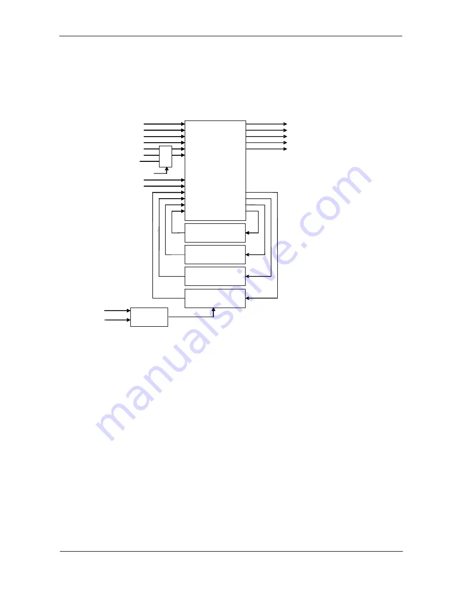
All input and output signals pass through the GPIO (General Purpose Input and Output) module.
The GPIO module consists of a Look-Up Table (LUT – Cross-Point Switch), 4 Pulse Generators and
a 12-bit counter. In the LUT, the relationship between inputs, counters and outputs is governed
by internal register set-up.
LUT
(
Cross
point switch)
LVAL IN
12bit
Counter
25MHz
Pixel Clock
xTTL_LVDS
Sel
DVAL IN
FVAL IN
EEN IN
HIROSE TTL IN 1
HIROSE TTL IN 2
LVDS IN
HIROSE TTL IN 3
Soft Trigger 0
Pulse Generator 3
(20bit Counter)
Pulse Generator 2
(20bit Counter)
Pulse Generator 1
(20bit Counter)
Pulse Generator 0
(20bit Counter)
CAMERA TRIGGER
CAMERA Ext. VD
CAMERA Ext. HD
HIROSE TTL OUT 1
HIROSE TTL OUT 2
LUT
(
Cross
point switch)
LVAL IN
LVAL IN
12bit
Counter
25MHz
Pixel Clock
xTTL_LVDS
Sel
DVAL IN
DVAL IN
FVAL IN
FVAL IN
EEN IN
EEN IN
HIROSE TTL IN 1
HIROSE TTL IN 1
HIROSE TTL IN 2
HIROSE TTL IN 2
LVDS IN
LVDS IN
HIROSE TTL IN 3
HIROSE TTL IN 3
Soft Trigger 0
Soft Trigger 0
Pulse Generator 3
The blocks shown in the above diagram have the following functionality:
6.1.1. LUT (Look Up Table)
The LUT works as a cross-point switch which allows connecting inputs and outputs freely. The
signals LVAL_IN, DVAL_IN, FVAL_IN and EEN_IN all originate from the camera timing circuit. The
signal CAMERA_TRIGGER is connected to the camera timing circuit, allowing a hardware trigger.
6.1.2. 12-bit Counter
A 25MHz clock or the camera pixel clock can be used as a source. The counter has a “Divide by
N”, where N has the range 1 through 4096, allowing a wide range of clock frequencies to be
programmed.
6.1.3. Pulse Generators (0 to 3)
Each pulse generator consists of a 20bit counter. The behavior of these signals is defined by
their pulse width, start point and end point.
The pulse generator signals can be set in either triggered or periodic mode.
In triggered mode, the pulse is triggered by the rising edge/falling edge/high level or low level
of the input signal.
In periodic mode, the trigger continuously generates a signal that is based on the configured
pulse width, starting point and endpoint.


