background image


Network Room Module Technical Bulletin 

14 

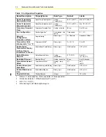
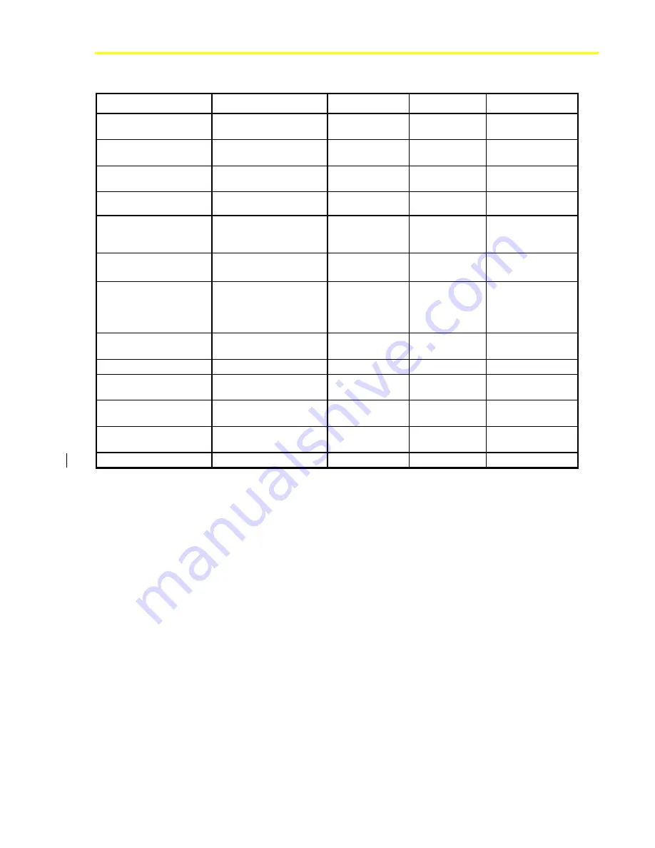
Table 7: Configuration Properties 

Name/Description 

Property Name 

Data Type 

Default 

Limits 

Space Temperature 
Setpoint High Limit 

SpaceTempSetptHighLimit Analog 

Temperature 

28.0°C (82.5°F) 

Max. 40°C (99.5°F) 

Space Temperature 
Setpoint Low Limit 

SpaceTempSetptLowLimit Analog 

Temperature 

12.0°C (53.5°F) 

Min. 0°C (32.0°F) 

Temporary Occupied 
Time 

TemporaryOccupiedTime 

Analog - minutes 

60 min 

0 to 255 min 

Fan Configuration 

FanConfiguration

1


Enumeration – fan 
speed 

Three speed 

0, 1, 2, 3 

Setpoint 
Configuration


(absolute or offset) 

SetpointConfig

2


Binary logic 

0 = Absolute 

Absolute or Offset 

Temperature Units 

(display units °C or °F) 

TemperatureUnits

3


Binary logic 

0 = SI (°C) 

SI or US 

Enable Space 
Temperature Display  

(defines if space 
temperature is shown) 

EnableSpaceTempDisplay Binary 

logic ON=Enabled 

OFF 

or 

ON 

Default Absolute 
Setpoint 

DefaultAbsoluteSetpt Analog 

temperature 

21°C (70°F) 

0 to 40°C 
(32 – 99.5°F) 

Back-light Time-out 

BackLightTime

4


Analog - seconds 

30 sec 

0 to 60 seconds 

Temperature Sensor 
Offset 

TemperatureOffset 

Analog – temp. 
diff. 

0°C 

±

5°C 

(

±

9°F) 

Enable Unoccupied 
State Blink  

EnableUnoccupiedBlinking Binary 

logic ON=Enabled 

OFF 

or 

ON 

Enable Maintenance 
Icon 

EnableMaintDispIcon Binary 

logic ON=Enabled 

OFF 

or 

ON 

Physical Address 

PhysicalAddress 

Integer 

191 

191 to 194 

1.  0=None, 1=One speed fan, 2=Two speed fan, 3=Three speed fan 

2.  0=Absolute Setpoint, 1=Offset Setpoint (±3°C) (±5°F) 

3.  0=SI (°C), 1=US (°F) 

4.  0=No back-light, >60=Back-light always on 

Summary of Contents for Facility Explorer

Page 1: ...Room Module 15 Introduction 15 North American Emissions Compliance 15 Key Concepts 16 Location of the Network Room Module 16 Dimensions of the Network Room Module 17 Wiring 18 Addressing 19 Service Port 20 Commissioning the Network Room Module 22 Procedure Overview 23 Detailed Procedures 23 Opening the Network Room Module 23 Mounting the NRM Directly on a Wall Surface 24 Mounting the NRM 80 x 80 m...

Page 2: ...Network Room Module Technical Bulletin 2 Troubleshooting 30 Specifications and Ordering Codes 31 Specifications and Technical Data 31 Ordering Codes 32 ...

Page 3: ...splay LCD to display the room temperature and local setpoint Graphical display symbols can indicate fan speed selection and the need for maintenance Optional operating controls include a dial to locally adjust the space temperature setpoint a push button to manually override the fan speed and a push button to select Fahrenheit F and Celsius C units of measure The NRM connects to the Remote Display...

Page 4: ...nt of the room command module are the operating controls and an LCD with three numerical digits and various operating mode symbols With the NRM you can view the space room temperature view and manually adjust the space temperature setpoint manually override the speed of the fan in the controlled equipment see when the controller is in the Off mode see when a maintenance condition exists request th...

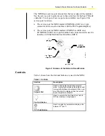
Page 5: ... LP NRM6xx 000C is a 6 pin Modular Jack connector and is used to interface with the Medium User Interface MUI Figure 2 Features of the Network Room Module Controls Table 1 shows how the dial and buttons are used in the NRM Table 1 Controls Control Description Setpoint Dial Used to change the temperature setpoint value turning right increases the setpoint and turning left decreases the setpoint Whe...

Page 6: ...nly Functions and Setup of the Network Room Module The NRM is a network device with no hardware inputs or outputs and connects to the Facility Explorer controller via the display or local link bus All the communication access and setup of the NRM is done through the controller where the NRM is connected The configuration properties of the NRM are set in the Room Sensor object in the controller whe...

Page 7: ...perature by rotating the dial The space setpoint value appears and blinks for a few seconds waiting for a change The NRM then confirms the change to the controller and displays the space temperature again if enabled In models with the fan speed override function you can change the fan speed by pressing the fan push button The fan status display cycles through the steps AUTO OFF Low Speed Medium Sp...

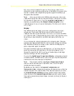
Page 8: ...d 82 5 F When you adjust the setpoint the value you enter is transmitted to the controller via either the network variable output Setpoint Output Absolute or Setpoint Output Offset depending on the value of Setpoint Configuration The network variable that is not used is set to an invalid value The Setpoint Output Absolute value when the NRM starts up is determined by the Default Absolute Setpoint ...

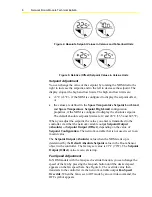
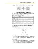
Page 9: ...peed is overridden to OFF by the user Fan in AUTO mode no override by user The actual fan speed is not shown The type of fan is configurable in the property Fan Configuration for None no fan There is no fan The fan override function is disabled Figure 7 Figure 7 No Fan Display One speed If you set the property to One speed fan pressing the fan push button cycles the fan status AUTO OFF and ON The ...

Page 10: ... See Figure 8 and Table 4 Figure 8 Occupancy Mode Icon for LP NRM5xx 000C and LP NRM6xx 000C Series NRMs Table 4 Effective Occupancy Status NRM Series Effective Occupancy Status Icon Description Occupied The display remains on LP NRM0xx 000C Series Unoccupied or Standby The display blinks off on approximately every 3 seconds Occupied LP NRM5xx 000C and LP NRM6xx 000C Series Unoccupied or Standby T...

Page 11: ...ncy Mode Request returns to the value of the Effective Occupancy Status input variable This operation depends on the correct configuration of the application in the controller using FX Builder Off Mode When the network variable input HVAC Application Mode has the OFF state 6 value the display shows OFF in the upper display field to indicate that no control action is possible Figure 9 OFF Mode Disp...

Page 12: ...uration property In NRM models with the F C push button the Temperature Units configuration property determines the temperature units on the display at start up but the units are toggled between F and C by pressing the push button Physical Address The NRM has a physical address that you must set in the PhysicalAddress configuration property in the Room Sensor object of the FX controller Non addres...

Page 13: ...tus 1 Enumeration Occupancy HVAC Application Mode HVACMode 2 Enumeration HVAC Mode Display Maintenance Icon MaintenanceIcon 3 Binary logic 1 0 Occupied 1 Unoccupied 2 Temp Occ Bypass 3 Standby 4 255 Invalid Null 2 6 Off All except 6 and 255 On 255 Invalid When Off the LCD shows OFF 3 0 Off 1 On 2 to 255 Invalid When On the LCD shows the maintenance icon Table 6 Network Variable Outputs Name Descri...

Page 14: ...s display units C or F TemperatureUnits 3 Binary logic 0 SI C SI or US Enable Space Temperature Display defines if space temperature is shown EnableSpaceTempDisplay Binary logic ON Enabled OFF or ON Default Absolute Setpoint DefaultAbsoluteSetpt Analog temperature 21 C 70 F 0 to 40 C 32 99 5 F Back light Time out BackLightTime 4 Analog seconds 30 sec 0 to 60 seconds Temperature Sensor Offset Tempe...

Page 15: ...st failure or malfunction of the NRM North American Emissions Compliance United States This equipment has been tested and found to comply with the limits for a Class A digital device pursuant to Part 15 of the FCC Rules These limits are designed to provide reasonable protection against harmful interference when this equipment is operated in a commercial environment This equipment generates uses an...

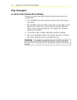
Page 16: ...nt to use the built in temperature sensor to measure space temperature For example there should be sufficient air circulation Avoid cold or warm air drafts radiant heat and direct sunlight Place some insulating material in the wiring access hole or conduit to prevent the introduction of air from outside the room IMPORTANT The installation of electrical wiring must conform to local codes and should...

Page 17: ...Network Room Module Technical Bulletin 17 Dimensions of the Network Room Module Figure 10 Network Room Module Dimensions mm in ...

Page 18: ...d LP NRM6xx 000C Series accept VDC power only Connect power to terminals 11 VDC or VAC and 14 VDC or VAC You may take power from the FX controller 15 VDC Note The COM terminal of the NRM is connected to the common potential of the FX controller If an independent power supply is used for the NRM ensure the proper connection of the multiple power supplies to avoid a short circuit through the NRM mod...

Page 19: ... voltage wiring close to transformers or high frequency generating equipment Addressing Non addressable NRM models have a fixed physical address of 191 For those models which are addressable the NRM s address must be set using its dual switch DIP switch block located on the printed wiring board See Figure 12 and Table 8 for details on addressing the NRM Note You must cycle power to the NRM disconn...

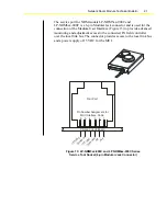
Page 20: ...odel number The service port for NRM model LP NRM0xx 000C is a 4 pin connector and is used for the connection of the FX Programming Key Figure 14 to download applications to the connected FX field controller over the local link bus The connector provides access to the local link bus and a power supply of 9 VDC for the Programming Key Figure 13 LP NRM0xx 000C Series Service Tool Socket 4 pin Connec...

Page 21: ...ed monitoring and adjustment access to the connected FX field controller over the local link bus The connector provides access to the local link bus and a power supply of 15 VDC for the MUI Pin Number Assignment for MUI Interface Cable Printed Circuit Board 1 5 V D C 2 3 4 5 6 1 R T R T C o m m o n 1 5 V D C Tool Port C o m m o n Figure 15 LP NRM5xx 000C and LP NRM6xx 000C Series Service Tool Sock...

Page 22: ...r User Guide LIT 12011154 for details on how to build an application and the corresponding network profile for either an N2 LON or BACnet MS TP network according to the network interface card installed in the FX controller Temperature Sensor During commissioning if you find that the internal temperature sensor does not read the exact value measured by a calibrated temperature monitor or you wish t...

Page 23: ...d in the kit Fix the base of the NRM to the surface mounting base using the two short screws provided in the kit Mount the NRM 80 x80 mm on a Recessed Wall Box Mounting Kit Turn the screws on the recessed wall box mounting kit to adjust the assembly to the depth of the wall box Insert the kit into the wall box and tighten the other screws until the prongs clamp properly in the wall box Mount the N...

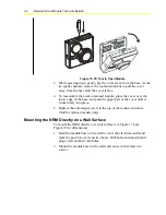
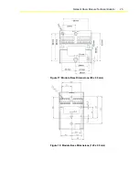
Page 24: ...e and push the upper part of the cover until it clicks firmly into place 5 Replace the anti tamper screw in the top of the module enclosure North American models only Mounting the NRM Directly on a Wall Surface To mount the NRM directly on a wall surface see Figure 17 and Figure 18 for dimensions 1 Hold the module base on the wall to cover the electrical outlet and mark the position of at least tw...

Page 25: ...Network Room Module Technical Bulletin 25 Figure 17 Module Base Dimensions 80 x 80 mm Figure 18 Module Base Dimensions 120 x 80 mm ...

Page 26: ...ing tool Figure 19 OB EN U P A B Figure 19 Notches and Drill Holes of Plastic Base 2 Mark the position of the holes B on the wall and drill holes 5 mm 20 in in diameter Figure 20 Insert plastic plugs wall anchors into holes 3 Position and fix the mounting base to the wall using the two long screws C provided in the kit Figure 20 Conduit D C Figure 20 Side View of Plastic Base with Module Base Moun...

Page 27: ...g Base Mounting the NRM 80 x 80 mm on a Recessed Wall Box To install the recessed wall box mounting kit see Figure 25 for dimensions 1 Turn the screws A to adjust distance D to match the depth of the wall box Figure 22 A D Figure 22 Side View of Wall Box Mounting Kit 2 Insert the kit into the wall box positioning it as shown in Figure 23 ...

Page 28: ...mp properly in the wall box 4 Mount the base of the module on the kit as shown in Figure 24 using the two screws included in the kit and inserting them into two opposite holes of the four holes marked C C Figure 24 Wall Box Mounting Kit with Module Base 12 78 Wall Box cdr Figure 25 Dimensions mm of the Recessed Wall Box Mounting Kit ...

Page 29: ...med If the NRM passes the self test the module begins to operate as configured with a display of space temperature or setpoint and fan symbol if supported If the NRM fails the self test the display continues to show all symbols 3 Connect the FX CommPro N2 LON or BACnet software tool to the FX controller to monitor the NRM network variables through the network profile as configured within the contr...

Page 30: ...fy that the configuration properties to enable the command are set correctly Using the FX CommPro Commissioning Tool check that the values of the network variable outputs from the Room Sensor object respond in accordance with the display changes as the dial is rotated or the fan push button is pressed Verify that the controller to which the NRM module is connected has been loaded with the correct ...

Page 31: ...es Recommended tightening torque 0 5 N m Temperature Sensor Pt1000 Class A DIN EN 60751 Range 0 to 40 C 32 to 104 F Accuracy better than 0 5 C 0 9 F with a display resolution of 0 5 C or 0 5 F Suitable for residential and commercial office environments only Display LCD Display with three digits and six symbols except temperature only models Controls Dial and push buttons depending on model Communi...

Page 32: ...e MUI and one NRM FX06 Rev A One MUI and one NRM FX07 One MUI and one NRM FX07 Rev A One MUI and one NRM FX14 One MUI and two NRMs 1 FX14 Rev A One MUI and two NRMs 1 FX14 Rev B One MUI and two NRMs 1 FX15 Universal NRM is not supported FX15 NRM is not supported FX15 Rev A NRM is not supported FX16 NRM is not supported FX16 Rev A NRM is not supported FX16 Rev B NRM is not supported FXVMA One MUI a...

Page 33: ...r surface mounting white TM 9100 8941 W Recessed wall box mounting kit white TM 9100 8951 W Panel mounting kit white NS WALLPLATE 0 Wall plate kit used to mount an 80 x 80 mm 3 15 x 3 15 in NRM onto a 2 x 4 in wall box TM 9100 8900 Europe T 4000 119 North America Special tool to open module LP KIT100 000C Programming Key The performance specifications are nominal and conform to acceptable industry...

Reviews: