CP6006-SA – User Guide, Rev. 0.5 Preliminary
// 56
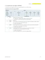
3.3.6.
Board ID Low Byte Register (BIDL)
Table 37: Board ID Low Byte Register (BIDL)
ADDRESS
0x28D
BIT
7
6
5
4
3
2
1
0
NAME
BIDL
ACCESS
R
RESET
0x40 (CP6006-SA) / 0x41 (CP6006X-SA)
BITFIELD
DESCRIPTION
7
BIDL
Board identification:
CP6006-SA:
0xB440
CP6006X-SA:
0xB441
3.3.7.
LED Configuration Register (LCFG)
The LED Configuration Register holds a series of bits defining the onboard configuration for the front panel General
Purpose LEDs.
Table 38: LED Configuration Register (LCFG)
ADDRESS
0x290
BIT
7
6
5
4
3
2
1
0
NAME
Reserved
LCON
ACCESS
R
R/W
RESET
0000
0000
BITFIELD
DESCRIPTION
3..0
LCON
LED3–0 configuration:
0000 = POST Mode (LEDs build a binary vector to display Port 80 signals)
0001 = General Purpose Mode (LEDs are controlled via the LCTRL register)
0010 = LEDs are dedicated to functions:
LED0: 10 Gigabit Ethernet controller port 1 link status
LED1: 10 Gigabit Ethernet controller port 0 link status
LED2: SATA LED
0011-1111 = Reserved
Beside the configurable functions described above, LED3–0 fulfill also a basic debug function during the power-up
phase as long as the first access to Port 80 is processed. For further information on reading the 8-bit uEFI BIOS POST
Code, refer to Chapter 2.7.1.3, “General Purpose LEDs”.


