32
www.lairdtech.com
Laird Technologies
BTM520/521
Bluetooth
®
Multimedia Plus Module
CONFIGURING
THE BTM520/521
3. Mic Input Gain
A microphone preamplifier which adds extra 20dB to input gain, is controlled by S-Register 415.
4. Mic Bias
Mic Bias will be enabled with S-Register 416.
Mic Bias Current is controlled by S-Register 417.
Mic Bias Voltage is controlled by S-Register 418.
5. Auxiliary DAC
The auxiliary DAC is enabled with S-Register 730.
The DAC output level is set by S-Register 731.
6. LED
The BT-MM+ module provides two dedicated output pins for LEDs (LED_EXT0, LED_EXT1).
Following modes are supported: LED_OFF, LED_ON, LED_PWM and LED_PULSE.
In LED_PWM mode, the parameters “Duty Cycle” an “PWM Period” can be specified via S-Registers.
This enables either a to dim the brightness of an LED (PWM Period=0) or to specify blinking with
defined on-time in a defined period (PWM Period > blinking visible for the eye)
In LED_PULSE mode, the brightness of an LED is modulated. Modulation speed is defined by
parameter “Pulse Rate” and maximum brightness is defined by parameter “Duty Cycle”.
Bluetooth Profiles
This section covers S-Registers and AT-Commands that are related to the supported Bluetooth Profiles on the
BT-MM+ module.
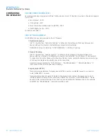
1. Profile Server Activation
In order to advertise available services to potential client devices, S-Register 102 is used.
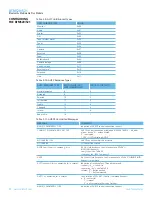
Supported profiles can be activated by setting the appropriate Flag in S-Register 102 (see Table 3 1).
After S-Register 102 has been written, all S-Registers must be saved to non-volatile memory (“AT&W”)
and subsequently a reset has to be carried out (“ATZ”).
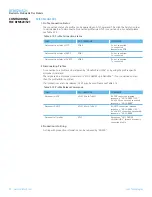
2. A2DP
The “Advanced Audio Distribution Profile” is used to transmit high quality audio streams between
two Bluetooth devices. An A2DP role must be assigned to a BT-MM+ module, either source or sink.
After this has been done, the appropriate service can be advertised. An attempt to advertise
A2DP-service without prior set up of a role will result in a (new) response error code 46.
An incoming A2DP connection request is accepted automatically if a valid link key for the paging
device exists. If no link key is available, Secure Simple Pairing (SSP, BT2.1) or legacy pairing (BT2.0
or earlier) is carried out, depending on the Bluetooth Version of the paging device.
After an A2DP connection has been established, the module remains in AT Command mode.
S Register 531 is ignored for A2DP connections.
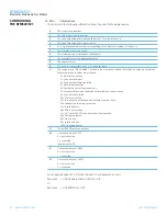
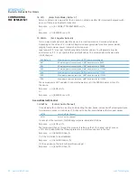
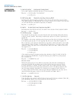
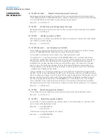
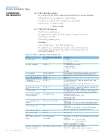
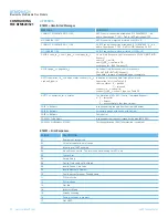
Table 3-5: LED S-Registers
TASK
AT-COMMAND / SREGISTER
COMMENT
Set LED_EXT0 mode
S335 [0..3], default=0
Mode:
0 = LED_OFF
1 = LED_ON
2 = LED_PWM
3 = LED_PULSE
Set LED_EXT1 mode
S340 [0..3], default=0
Set LED_EXT0 Duty Cycle
S336 [0..4095], default = 2048
referenced if LED mode = LED_PWM
or LED_PULSE
Set LED_EXT1 Duty Cycle
S341 [0..4095], default = 2048
Set LED_EXT0 PWM Period
S337 [0..15], default = 0
referenced if LED mode = LED_PWM
Set LED_EXT1 PWM Period
S342 [0..15], default = 0
Set LED_EXT0 Pulse Rate
S338 [0..15], default = 0
referenced if LED mode = LED_PULSE
Set LED_EXT1 Pulse Rate
S343 [0..15], default = 0

