background image

- 7 - 

Programming the Magnetic Stripe Reader 

 
The integrated MSR is programmable to meet specific requirements of different software.  The default 
output format of the MSR is set to a common protocol that is compatible with most software.  
Programming of the MSR may not be necessary.  Before editing the MSR parameters, please refer to the 
user manual of the Point-of-Sale software or credit card verification software to find out what are the 
requirements on the output format. 
 
To install the programming utility, run the "Setup" program in the utility package.  Select destination folder 
and click "START" to start the installation  process. Skip any warning message dialog boxes by clicking 
"Yes" or "Continue". When installation is completed, reboot the computer. The utility program file 
MREdit.exe will be copied to the harddisk in the installation target folder (default is C:\Program Files\Logic 
Controls). 
 
To program the MSR for specific output format, follow the procedure below: 
 
1.  Start the Programming Utility by double clicking on the "MREdit.exe" icon in the folder where the utility 

is installed. 

 
2.  A new parameter template can be prepared on the screen by editing the parameters to be used. 

Alternatively, an old template can be brought into the utility for editing. Either OPEN from a .MTL file or 
READ from the magnetic stripe reader. To open an old .MTL file, click on [File] --> [Open] on the Menu 
bar or click on the "File Open" icon on the toolbar.  To read from the MSR, click [Access MR] --> [Read 
from MR] on the Menu bar or click on the "Read from MR" icon on the toolbar. 

 
4.  After editing the parameters, it is advised that the template should be first saved into a .MTL template 

file for future reference and for programming multiple number of magnetic stripe readers. Then, click 
[Access MR] --> [Write into MR] on the Menu bar or click on the “Write to MR” icon on the toolbar to 
write the template into the magnetic stripe reader. 

 
5.  To test the programmed magnetic stripe reader output, open HyperTerminal and swipe a magnetic 

stripe card across the reader.  The output will appear in HyperTerminal screen.  Check that the output 
format is correct as programmed. 


Summary of Contents for LA3000 Series

Page 1: ...i Logic Controls All in One POS Touch Terminal USER MANUAL LA3000 Series...

Page 2: ...ument is subject to change without notice and does not represent a commitment on the part of the manufacturer FCC NOTICE This device complies with Part 15 of FCC Rules Operations are subject to the fo...

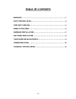
Page 3: ...E OF CONTENTS OVERVIEW 1 SAFETY INSTRUCTIONS 2 CARE AND HANDLING 3 PRODUCT FEATURES 4 HARDWARE INSTALLATION 5 SOFTWARE INSTALLATION 6 TOUCH MONITOR ADJUSTMENTS 8 TROUBLESHOOTING 12 TECHNICAL SPECIFICA...

Page 4: ...h terminal The LCD monitor incorporates 15 color active matrix thin film transistor TFT liquid crystal display to provide superior display performance A maximum resolution of XGA 1024x768 is ideal for...

Page 5: ...n outlet that has not been configured for this purpose Do not use a damaged power cord Use only the power cord that comes with the unit Use of an unauthorized power cord may invalidate warranty 6 Do n...

Page 6: ...ressed air To clean the display unit cabinet use a cloth lightly dampened with a mild detergent Do not immerse unit in water Avoid getting liquids inside your all in one touch terminal If liquid does...

Page 7: ...Compatible with VGA SVGA XGA non interlaced 5 wire resistive touch panel High contrast with 400 1 ratio Anti scratch and anti glare coatings on screen surface Advanced OSD control for picture quality...

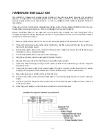
Page 8: ...ideo cable audio cable USB cable and DC power cord through the oval hole at the front of the monitor stand 3 Connect the video cable to touch monitor VGA connector Tighten by turning the two thumb scr...

Page 9: ...m Please download and unzip the suitable driver files before installation There are two types of drivers available If the POS software is only able to access COM ports for the pole display use the Vir...

Page 10: ...elow 1 Start the Programming Utility by double clicking on the MREdit exe icon in the folder where the utility is installed 2 A new parameter template can be prepared on the screen by editing the para...

Page 11: ...er contrast adjustment b Move to next item clockwise c Increase value of the parameter selected for adjustment 3 a Enter brightness adjustment b Move to next item counter clockwise c Decrease value of...

Page 12: ...Increases or decreases snow noise of the image if necessary after auto adjustment CLOCK Fine adjust dot clock if necessary after auto adjustment OSD H POSITION Moves OSD menu position horizontally on...

Page 13: ...f a monitor is the resolution level at which the LCD panel is designed to perform best It is the actual number of pixels horizontally in the LCD by the number of pixels vertically in the LCD For the L...

Page 14: ...wer consumption when not in use We recommend switching the monitor off when it is not in use for a long time Power Mode Consumption On 30W Sleep 4W Off 2W NOTE The monitor automatically goes through t...

Page 15: ...Refer to the About Touchmonitor Adjustments section to adjust the brightness The screen is blank During operation the monitor screen may automatically turn off as a result of the Power Saving feature...

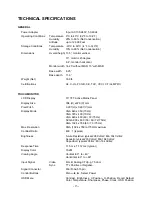
Page 16: ...splay Size 304 H x228 V mm Pixel Pitch 0 297 H x 0 297 V mm Display Mode VGA 640 x 350 70Hz VGA 720 x 400 70Hz VGA 640 x 480 60 72 75Hz SVGA 800 x 600 56 60 72 75Hz XGA 1024 x 768 60 70 75Hz Max Resol...

Page 17: ...thout failure using a stylus similar to a finger Optical Light Transmission Typically 85 at 550 nm wavelength visible light spectrum per ASTM D1003 Visual Resolution All measurements made using USAF 1...

Page 18: ...onal Interface USB HID keyboard emulation COMPUTER BOARD Processor Intel Celeron M 800MHz to 1 5GHz Memory 128MB to 1GB DDR Video 1024x768 pixels 24 bit color Network Interface 10 100 Base T Ethernet...

Reviews: