MAX32600 User’s Guide
Pulse Train Engine
9
Pulse Train Engine
9.1
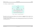
Pulse Train Engine (PTE) Overview
The
MAX32600
includes 13 separate pulse train generators. Eight of these (PT0 - PT7) can be used to generate output sequences on
pins.
The remaining five are routed to the Analog Front End (AFE). For details on how the pulse trains (PT8 - PT11 and PT15) are used by the AFE, refer to
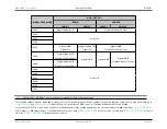
Each pulse train generator can be set to output either a square wave or a repeating pattern from 2-bits to 32-bits in length. The frequency of each enabled pulse train
generator is also set separately, based on a divide down (divide by 2, divide by 4, divide by 8, etc.) of the Pulse Train Peripheral Clock.
Any single pulse train generator or any desired group of pulse train generators can be restarted at the beginning of their patterns and synchronized with one another
enabling each synchronized pulse train generator to start simultaneously.
9.2
Output Mode Selection
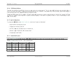
Two modes of operation are supported:
and
. Both modes use a rate counter that defines the number of system clock cycles that occur
before the output state is changed. In both modes, setting the
to 0 disables all active pulse trains. See
Enabling and Disabling Pulse Train
for further information.
9.3
Pulse Train Peripheral Clock Rate Configuration
The
MAX32600
supports a programmable Pulse Train Peripheral Clock Rate (PTE
PCLK
). Each of the 13 pulse trains use the Peripheral Clock as the source to set
their individual rate control as described in the
section. To select the peripheral clock rate, write the Pulse Train Clock Control register,
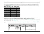
, with the value desired to achieve the ideal clock for your application. The rate is a divisor (4-bits) of the system clock as shown in the
below.
Pulse Train Peripheral Clock Selection Table
pulse_train_clk_scale (4-bit value)
PT Peripheral Clock Rate (PTE
PCLK
)
0
Disables Pulse Train Peripheral Clock
1
24MHz
2
12MHz
3
6MHz
4
3MHz
Rev.1.3 April 2015
Maxim Integrated
Page 489


