Operation of Board Components
2 4
R e v i s i o n 3
User LEDs
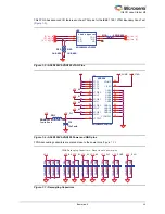
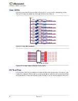
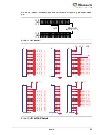
Eight active low debug LEDs are provided on the board. You can remove the corresponding jumpers
from the 8 x 2 headers to detach any of the eight LEDs from the FPGA I/O.
I/O Test Pins
All IGLOO nano FPGA I/Os are available on headers located on the top and bottom of the device. These
headers are multiples of 100 mils apart, so you can easily place an extension card on top with an off-the-
shelf bread board for a low-cost integration solution. Before you can use the I/Os assigned to the LEDs,
Figure 3-9 • User LEDs Schematic
Figure 3-10 • Jumper Header Schematic for User LEDs
led1
led2
led3
led4
led5
led6
led7
led8
VCC_3_3
1
2
LED2
RED SMD LED - 1206
LED2
RED SMD LED - 1206
R31
470R-0603
R31
470R-0603
1
2
LED5
GREEN SMD LED - 1206
LED5
GREEN SMD LED - 1206
1
2
LED1
RED SMD LED - 1206
LED1
RED SMD LED - 1206
R34
470R-0603
R34
470R-0603
1
2
LED6
GREEN SMD LED - 1206
LED6
GREEN SMD LED - 1206
1
2
LED3
RED SMD LED - 1206
LED3
RED SMD LED - 1206
R35
470R-0603
R35
470R-0603
R32
470R-0603
R32
470R-0603
1
2
LED7
GREEN SMD LED - 1206
LED7
GREEN SMD LED - 1206
1
2
LED4
RED SMD LED - 1206
LED4
RED SMD LED - 1206
R36
470R-0603
R36
470R-0603
R33
470R-0603
R33
470R-0603
1
2
LED8
GREEN SMD LED - 1206
LED8
GREEN SMD LED - 1206
R37
470R-0603
R37
470R-0603
R30
470R-0603
R30
470R-0603
led1
led2
led4
led3
led7
led6
led5
led8
agl_b2_p35 [4,8]
agl_b2_p36 [4,8]
agl_b2_p40 [4,8]
agl_b2_p41 [4,8]
agl_b2_p42 [4,8]
agl_b2_p43 [4,8]
agl_b2_p44 [4,8]
agl_b2_p45 [4,8]
1
2
3
4
5
6
7
8
9
10
11
12
13
14
15
16
JP13
8x2 Header for Jumper
JP13
8x2 Header for Jumper
Summary of Contents for IGLOO nano Starter Kit
Page 1: ...IGLOO nano Starter Kit User s Guide ...
Page 6: ......
Page 9: ...IGLOO nano Starter Kit Revision 3 9 Figure 1 3 Bottom Silkscreen ...
Page 14: ......
Page 28: ......
Page 30: ......
Page 32: ......
Page 34: ......
Page 36: ......
Page 41: ......

