Chapter 11. Embedded Programmable Interrupt Controller (EPIC) Unit
11-13
EPIC Timers
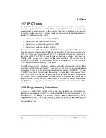
11.7 EPIC Timers
The MPC8240 has appropriate clock prescalers and synchronizers to provide a time base
for the four global timers (0–3) of the EPIC unit. The global timers can be individually
programmed to generate interrupts to the processor when they count down to zero and can
be used for system timing or to generate regular periodic interrupts. Each timer has four
registers for configuration and control:
•
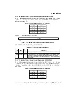
Global timer current count register (GTCCR)
•
Global timer base count register (GTBCR)
•
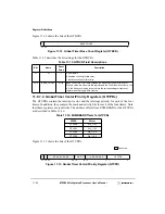
Global timer vector/priority register (GTVPR)
•
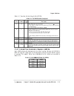
Global timer destination register (GTDR)
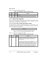
The timers count at 1/8 the frequency of the SDRAM_CLK signals. The EPIC unit has a
timer frequency reporting register (TFRR) that can be written by software to store the value
of the timer frequency (as described in Table 11-11). Although this frequency is affected by
the setting of the PLL_CFG[0:4] signals at reset, the system software must know the
SDRAM_CLK frequency in order to set this value accurately. (There is no way to
determine this frequency by simply reading an MPC8240 register.) The value written to
TFRR does not affect the frequency of the timers.
Two of the timers, timer 2 and timer 3, can be set up to start automatically periodic DMA
operations for DMA channels 0 and 1, respectively, without using the processor interrupt
mechanism. In this case, the timer interrupt should be masked (GTVPR[M] = 1), and
GTBCR[CI] should be cleared to start the counting. It is important to choose a rate for the
timer so the time between the interrupts is longer than the time required to complete the
DMA chain; otherwise, unpredictable operation occurs. To complete the initialization of
the periodic DMA feature, the DMA channel must be configured for chaining mode and the
DMR[PDE] for the appropriate channel must be set. See Section 8.3.2.2, “Periodic DMA
Feature.”
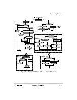
11.8 Programming Guidelines
Accesses to the EPIC unit include interrupt and timer initialization, and reading the
interrupt acknowledge register (IACK), which results in the EPIC unit returning the vector
associated with the interrupt to be serviced. External interrupt sources IRQ[0:4] can be
programmed for either level- or edge-sensitive activation and either polarity. Similarly, all
16 serial interrupt sources can be programmed for either level- or edge-sensitive activation
and for either polarity.
Summary of Contents for MPC8240
Page 1: ...MPC8240UM D Rev 1 1 2001 MPC8240 Integrated Processor User s Manual ...
Page 38: ...xviii MPC8240 Integrated Processor User s Manual TABLES Table Number Title Page Number ...
Page 48: ...xlviii MPC8240 Integrated Processor User s Manual Acronyms and Abbreviations ...
Page 312: ...6 94 MPC8240 Integrated Processor User s Manual ROM Flash Interface Operation ...
Page 348: ...7 36 MPC8240 Integrated Processor User s Manual PCI Host and Agent Modes ...
Page 372: ...8 24 MPC8240 Integrated Processor User s Manual DMA Register Descriptions ...
Page 394: ...9 22 MPC8240 Integrated Processor User s Manual I2O Interface ...
Page 412: ...10 18 MPC8240 Integrated Processor User s Manual Programming Guidelines ...
Page 454: ...12 14 MPC8240 Integrated Processor User s Manual Internal Arbitration ...
Page 466: ...13 12 MPC8240 Integrated Processor User s Manual Exception Latencies ...
Page 516: ...16 14 Watchpoint Trigger Applications ...
Page 538: ...B 16 MPC8240 Integrated Processor User s Manual Setting the Endian Mode of Operation ...
Page 546: ...C 8 MPC8240 Integrated Processor User s Manual ...
Page 640: ...INDEX Index 16 MPC8240 Integrated Processor User s Manual ...

