background image

©

 National Instruments Corporation

9

NI 9237 Calibration Procedure

4.

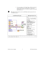
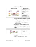
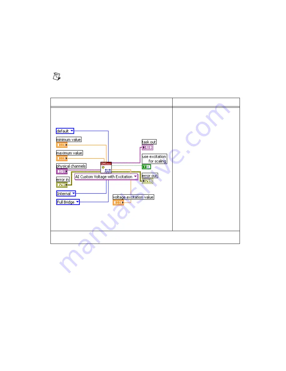
Create and configure an AI Custom Voltage with Excitation channel 
using the DAQmx Create Virtual Channel VI, as shown in the 
following table. Use Table 4 to determine the minimum and maximum 
values for the device.

Note

Throughout the procedure, refer to the NI-DAQmx function parameters for the 

LabVIEW input values.

LabVIEW Block Diagram

NI-DAQmx Function Call

Call 

DAQmxCreateAIVoltageChan

WithExcit

 with the following 

parameters:

taskHandle

taskHandle

physicalChannel

dev1/ai0

nameToAssignToChannel

myVoltageChannel

terminalConfig

DAQmx_Val_Cfg_Default

minVal

–0.025

maxVal

0.025

units

DAQmx_Val_Volts

bridgeConfig

DAQmx_Val_FullBridge

voltageExcitSource

DAQmx_Val_Internal

voltageExcitVal

:

*


2.5

3.3

5.0

, or 

10.0

useExcitforScaling

TRUE

customScaleName

NULL

*

Use the excitation value that corresponds to the calibrator voltage value you set in step 2. Refer to Table 4 for corresponding 

excitation setting and calibrator output values.

Summary of Contents for 9237

Page 1: ...ler specific instructions and detailed function explanations You can install these help files when you install NI DAQmx on the calibration computer Contents Conventions 2 Software 2 Documentation 3 Calibration Interval 3 Test Equipment 4 Test Conditions 4 Calibration Procedure 5 Calibration Process Overview 5 Initial Setup 5 Verification Procedure 6 Specifications 12 Test Limits 12 Using the Table...

Page 2: ...ng examples and syntax examples This font is also used for the proper names of disk drives paths directories programs subprograms subroutines device names functions operations variables filenames and extensions monospace italic Italic text in this font denotes text that is a placeholder for a word or value that you must supply Software Install NI DAQmx 8 1 or later on the calibration computer NI D...

Page 3: ...software and NI DAQmx supported DAQ devices and how to confirm that your device is operating properly To access this guide select Start All Programs National Instruments NI DAQ DAQ Getting Started Guide Note The documents above are installed with NI DAQmx You can also download the latest versions from the NI Web site at ni com manuals NI 9237 Operating Instructions This document describes how to u...

Page 4: ...nt temperature Keep relative humidity below 80 Allow a warm up time of at least 10 minutes to ensure that the measurement circuitry is at a stable operating temperature Table 1 Recommended Equipment Equipment Recommended Model Requirements Calibrator Fluke 5700A If this instrument is unavailable use a high precision voltage source with an accuracy of at least 10 ppm and an output impedance of less...

Page 5: ...justment The first two steps are explained in the following sections Initial Setup You must configure the device in Measurement Automation Explorer MAX to communicate with NI DAQmx Complete the following steps to configure a device in MAX 1 Install the NI DAQmx driver software 2 Make sure that no power is connected to the module terminals If the system is in a nonhazardous location the chassis pow...

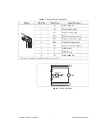
Page 6: ...lowing steps to test the performance of the device 1 Make the following connections on the NI 9949 terminal block Insert one leg of each 350 Ω resistor into AI Insert the second leg of one 350 Ω resistor into EX Insert the second leg of the other 350 Ω resistor into EX Connect RS to EX Connect RS to EX Connect the positive input of the DMM to RS Connect the negative input of the DMM to RS Connect ...

Page 7: ...cription 1 SC Shunt calibration 2 AI Positive analog input 3 AI Negative analog input 4 RS Positive remote sense input 5 RS Negative remote sense input 6 EX Positive excitation output 7 EX Negative excitation output 8 T TEDS DATA 9 T TEDS Return 10 SC Shunt calibration These signals are shared by all four RJ 50 connectors on the NI 9237 EX RS RS EX DMM AI Calibrator Guard AI ...

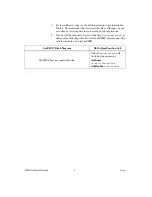
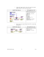
Page 8: ...ing only the values used in your application 3 If you use C function calls create a task using DAQmxCreateTask as shown in the following table If you use LabVIEW skip this step The task is created in step 4 in LabVIEW LabVIEW Block Diagram NI DAQmx Function Call LabVIEW does not require this step Call DAQmxCreateTask with the following parameters taskName AIVerificationTask taskHandle taskHandle ...

Page 9: ...agram NI DAQmx Function Call Call DAQmxCreateAIVoltageChan WithExcit with the following parameters taskHandle taskHandle physicalChannel dev1 ai0 nameToAssignToChannel myVoltageChannel terminalConfig DAQmx_Val_Cfg_Default minVal 0 025 maxVal 0 025 units DAQmx_Val_Volts bridgeConfig DAQmx_Val_FullBridge voltageExcitSource DAQmx_Val_Internal voltageExcitVal 2 5 3 3 5 0 or 10 0 useExcitforScaling TRU...

Page 10: ... DAQmx Start Task VI as shown in the following table LabVIEW Block Diagram NI DAQmx Function Call CallDAQmxCfgSampClkTiming with the following parameters taskHandle taskHandle source NULL rate 50000 activeEdge DAQmx_Val_Rising sampleMode DAQmx_Val_FiniteSamps sampsPerChan 10000 LabVIEW Block Diagram NI DAQmx Function Call Call DAQmxStartTask with the following parameter taskHandle taskHandle ...

Page 11: ...p 7 to the upper limit and lower limit values you calculated in step 9 If the result is between these values the device passes the test 11 Clear the acquisition using the DAQmx Clear Task VI as shown in the following table 12 Repeat steps 2 through 11 for all voltage values all excitation values and all channels 13 Disconnect the calibrator and the DMM from the device LabVIEW Block Diagram NI DAQm...

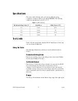
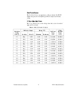
Page 12: ... Setting Value is the voltage value to enter in the DAQmx Create Virtual Channel VI in step 4 Calibrator Output The Calibrator Output is the voltage value that you source into the NI 9237 for verification purposes This value is broken down into two columns Location and Value Location refers to where the value fits within the test range Value refers to the voltage value to be verified Max refers to...

Page 13: ... Output Range V V Test Point Value V V 1 Year Absolute Error V V Location Value V Minimum Maximum 2 5 Max 0 055 0 025 0 025 0 022000 0 000063 2 5 Mid 0 000 0 025 0 025 0 000000 0 000033 2 5 Min 0 055 0 025 0 025 0 022000 0 000063 3 3 Max 0 073 0 025 0 025 0 022000 0 000036 3 3 Mid 0 000 0 025 0 025 0 000000 0 000010 3 3 Min 0 073 0 025 0 025 0 022000 0 000036 5 0 Max 0 110 0 025 0 025 0 022000 0 0...

Page 14: ...onal Instruments also has offices located around the world to help address your support needs For telephone support in the United States create your service request at ni com support and follow the calling instructions or dial 512 795 8248 For telephone support outside the United States contact your local branch office Australia 1800 300 800 Austria 43 662 457990 0 Belgium 32 0 2 757 0020 Brazil 5...

Reviews: