Chapter 4
General-Purpose Counter/Timer
DAQ-STC Technical Reference Manual
4-86
©
National Instruments Corporation
4.8.11.16 Frequency Shift Keying
To use this function, set G_CONTROL conditioning to level gating and program the counter
to reload on TC and switch the load bank selection on G_CONTROL. The counter begins
decrementing after the ARM. Whenever counter TC is reached, the counter reloads and
counts down to TC again. G_GATE is synchronized by the falling edge of G_SOURCE to
generate G_CONTROL. G_CONTROL affects the bank-select signal, which indicates
whether the reload occurs from bank X or Y. The load-select signal indicates whether the
reload occurs from load register A or B.
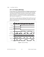
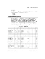
Figure 4-47 shows an example of frequency shift keying. When G_GATE is low, pulses are
generated with a pulse interval of three and a pulsewidth of two. When G_GATE is high,
pulses are generated with a pulse interval of five and a pulsewidth of four. The dotted line
indicates where the ARM occurs.
Figure 4-47.
Frequency Shift Keying
Counter Value
Counter Load
G_SOURCE
G_GATE
G_CONTROL
Load Select
Counter TC
G_OUT
Bank Select
2
1 0 1 0 2 1 0 1 0 4 3 2 1 0 3 2 1 0 4 3 2 1 0 3 2 1 0


