Operator Level Parameter Definitions:
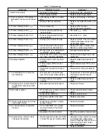
PV - Process Value This is the temperature (or other
process variable) as measured at the sensor. This will
indicate a value within the range between the low scale
(Lo.SC) and high scale value (hi.SC). This indication
will read an error code if the temperature (process
variable) goes out of the preset span. Note items 6 and
7 of the troubleshooting guide on page 25 for the error
code descriptions.
SV - Set Point Value This parameter is the desired set
point of the process. It can be adjusted within the
range defined by the low scale (Lo.SC) and high scale
value (hi.SC). The span adjustments can be used to
limit the set point of the controller.
ASP1 - Alarm 1 Set Point Value or Dwell Time This
sets the points at which alarm 1 will energize if A1.SF
(alarm 1 special function) is set for an alarm function.
If A1.SF is selected for the dwell timer function (toon or
toof), then this becomes the timer setting in minutes.
The dwell timer starts counting when the process value
reaches the set point value. Note page 20 for more
information.
rAMP - Ramp Rate This controls the heat-up and
cool-down rate of the process. This setting is in
degrees per minute.
oFSE - Offset Value This parameter is only functional
if the integral time (automatic reset) is set to zero. The
oFSE then functions the same as manual reset to
correct the process temperature to the set point temper-
ature. If the process temperature stabilizes below the
set point, then set a positive amount of oFSE. If the
process temperature stabilizes above the set point, set
a negative amount of oFSE. Wait for the system to
stabilize and make further adjustments as required.
ASP2 - Alarm 2 Set Point Value This sets the points
at which alarm 2 will energize if A2.SF (alarm 2 special
function) is set for an alarm function. If A2.SF is
selected for cooling; the cooling cycle time, proportional
band and deadband are adjusted by parameters CCyC,
C.pb and d-b. ASP2 will then have no effect. Note
page 20 for more information.
ShiF - Display Shift A value entered here will be
added or subtracted from the process value. This offset
can be used as a correction factor if the sensor does
not read the same temperature as the item being
sensed. Note page 21 for more information.
Pb, Ei and Ed - PID Values Proportional band,
Integral (reset) and Derivative (rate) time constants.
These must be set as close as possible to the process
application requirements. Note page 17 for more
information.
AhY1, AhY2 - Hysteresis of Alarm 1 and Alarm 2
The values entered here define the deadbands for the
alarms. The alarms will not change state until the
temperature is outside of the deadband.
hySE - Hysteresis of On-Off Control This parameter
defines the deadband when on-off control is used and
PID control has been disabled. For on-off control, set
Pb, Ei and Ed to 0. The output on a relay control will
not change state until the temperature is outside the
deadband. Note page 17 for further information.
Addr - Interface Address For external communica-
tions with a computer.
Lo.SC, hi.SC - Low/High Scale Range These
parameters are used to define the range (span) of the
control. These should be set for the requirements and
safety of your process. Refer to "Initial Operation" on
page 17 for further information. If inputs other than
thermocouples or RTDs are required, refer to page 22
for reranging directions.
PL.1, PL.2 - Power Limit These parameters are used
to limit the output percentage of power for heating or
cooling. If the control has relay or pulsed voltage
outputs, then the percentage of “on” time will be
decreased. The actual output levels will be decreased
if the control has linear current (4-20mA) or linear
voltage outputs.
inPE - Input Type This parameter is used to program
the control to the type of input sensor used.
uniE - Process Units This parameter is used to set
the display in degrees F, C or blank for engineering
units.
rESo - Display Resolution This parameter is used to
place a decimal point in the process and set point
values. A two-place decimal point can only be set if the
uniE adjustment is set to engineering units (PU).
Con.A - Control Action of Output 1 This parameter
selects heating (reverse) or cooling (direct) action for
output 1.
A1.Md, A2.Md - Alarm Mode Selection for Alarm 1
and Alarm 2 This adjustment sets the type of alarm
required: deviation alarm, band alarm or process alarm.
Refer to page 20 for more information.
A1.SF - Alarm 1 Special Function This selects
special functions required for use with alarm 1. The
special functions include latching alarms, hold
(inhibited) function or dwell timer function. Refer to
page 20 for more information on alarms.
A2.SF - Alarm 2 Special Function This selects spe-
cial functions for alarm 2. This includes latching func-
tion, hold (inhibited) function or proportional cooling.
CyC - Proportional Cycle Time of Output 1 This sets
the proportional cycle time for output 1. This should be
set according to the type of output device used. For
mechanical relays, cycle times of 15 to 20 seconds are
used. For solid-state relays, set this adjustment to 1 or
0. For 4-20mA or other linear outputs set this to 0.
CCyC - Cooling Cycle Time Only used if A2.SF
(alarm 2 special function) has been set for cooling. Use
the same settings as the above paragraph.
C.Pb, d-b Cooling Proportional Band, Cooling
Deadband Only used if A2.SF (alarm 2 special
function) has been set for cooling. Refer to page 22 for
further information on the settings to be used for cooling
output.


