21 |
P a g e
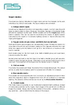
Input modes
The inputs are factory defaulted to toggle mode and can be changed via the web
interface or by TCP/IP commands. The input modes work as follows.
1.
Independent inputs
Inputs can be detached from their corresponding outputs, in which case they will
have no direct effect on them. However, the status changes of the digital inputs
will still be reported via the open TCP/IP sockets and on the Input page of the
built-in website. This can be used for monitoring the status of digital sensors
connected to the inputs or to activate lighting scenes or macros whenever the
input gets triggered.
2.
Toggle mode single colour and RGB (factory default)
Each short button press toggles the corresponding output. Holding the button for
more than 0.5s will dim up and down (always in the opposite direction then last
time) the output until the button is let go of or the minimum or maximum dim
level is reached.
Each double press on the first input of an RGB or RGBW group will recall basic
colours one after the other.
Double press and hold on the first input of an RGB or RGBW group will cause the
output to swipe through all colours. This allows you to set the output to any colour
you want. You should let off the input once the desired colour is reached.
3.
Follow mode
The status the outputs will follow the state of the corresponding input. The output
will be on while the momentary switch is pressed and off while it is released.
4.
Monostable mode
The outputs can be programmed to turn on only for an adjustable amount of time
when the respective input is triggered then turn off. An example is a staircase
lighting. The duration of this interval can be set by the Monostable Duration.
5.
Switch mode
This mode makes it possible to use maintained (standard light switches) instead
of momentary switches on the inputs. Each trigger of the switch (On or Off) will
toggle the outputs. Please note that the position of the switch – similarly to three-
way switches – will not determine the status of the output.
Summary of Contents for FNIP-12xPWM
Page 3: ...3 P a g e ...
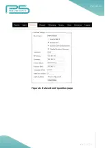
Page 13: ...13 P a g e Figure 6 Network configuration page ...

