11. (AMG)MG900 Series MODUS Communication Protocol
1.Protocol Introduction
1.1 Scope of selection: pan-globe M2000 series communication instrument
1.2 Work realization: data exchange between instrument and host computer (instrument can only be used as slave to receive interrogation and reply)
1.3 Serial transmission mode: RTU
1.4 Transmission interface: RS485
1.5 Communication medium: shielded twisted pair
1.6 Communication stack number: 1~255. The upper limit of the number of connecting meters is related to the load capacity of the host
1.7 Function code implementation: read hold register (03), write single register (06), write multiple registers (10)
1.8 Data length: 1) when writing data to the machine, a maximum of 16 consecutive menus (32 bytes) can be written at one time.
2) when reading the menu data inside the machine, the non-programmed menu can read 16 consecutive menus at a time (the unrealized address
outside the parameter address table is 0), while the programmed menu can only read 16 consecutive menus at a time
1.9 Numerical format: signed 16-bit binary complement;The data read is 10.0 times larger;Before writing the data, enlarge the data 10.0 times
before sending it; Notice the transition
1.10 serial port parameters: 1), baud rate :4800, 9600, 19200, 38400, 76800, 153600 2) start position: 1 3) data bit: 8
4) check bit: E(even check), N(no check) 5) stop bits: 1, 2
1.11 Frame check method: cyclic redundancy check (CRC16)
1.12 Message format (N=2 here)
Address
Function code
Data
CRC check
8 bits
8 bits
N*8 bits
16 bits
Note:
1
、
read AM and AM1(cold control manual) menus,0 represents manual state,1 represents automatic state.
2
、
RAP is the program control menu, read, return 0X0000 represents the program control close, return 0X0001 represents the
program control start: write 0X0000 to close the program control, write 0X0001 to start the program control, write 0X0002 to stop the program control,
write 0X0002 to end the suspension, continue to run the program control.
3
、
Before writing the program-controlled menu, please write 0x0000 to RAP to close the program-controlled menu.
4
、
Before writing MV/MV1 threshold, please first write 0x0000 to AM/AM1 to make the system switch to manual control.
5
、
When the multiplier is 10, the returned data is magnified 10 times.
6
、
PV1 and PV2 are read-only parameters.
7
、
There should be a time interval between write parameter instructions, no matter the same address or not, which may cause instrument failure, and the time
interval should be no less than 150 milliseconds.
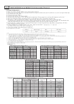
2.Example
1. Function code 03(read value SV=100.0)
2. Function code 06(write value SV=100.0)
3. Function code 10(write constant SV=100.0)
Request
Reply
Request
Request
Reply
Reply
Segment Number
Segment Number
Segment Number
Hexadecimal
Machine Number
Function code
Initiate Address Hi
Initiate Address Lo
Register Number Hi
Register Number Lo
Byte Count
Segment Number Hexadecimal
Hexadecimal
Hexadecimal
Hexadecimal
Hexadecimal
Segment Number
Segment Number
Machine Number
Function code
Register Number Hi
Register Number Lo
Register Number Lo
Register Number Hi
Register Number Lo
Register Number Hi
Register Number Hi
Register Number Hi
Register Number Lo
Register Number Lo
Register Number Lo
Register Number Hi
Machine Number
Machine Number
Function code
Function code
Initiate Address Hi
Initiate Address Hi
Initiate Address Hi
Initiate Address Hi
Initiate Address Lo
Initiate Address Lo
Machine Number
Machine Number
Function code
Function code
Initiate Address Lo
Initiate Address Lo
Byte Count
3. Parameter Address Distribution Table(”NC” represent blank address)
Parameter
Name
Address
Hexadecimal
Decimal
Read write
Status
Ratio
Scale (No override)


