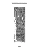
background image

ICI16• 5 

ICI16 THEORY OF OPERATION 

At first look the ICI16 may seem quite simple, but there is actually quite a bit 

to it on the “inside” of the components. Many items are inside the IR receiver 
part (U3/4) and if built up with discrete components it would never fit in this 
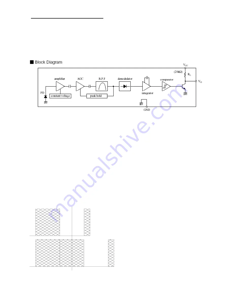
little kit. Inside this part there’s an IR detector diode, amplifier, AGC circuit, 
band pass filter, a peak-hold circuit, an integrator, comparators, and an output 
amp. Heck, the part is a kit in itself! Just be glad it is in one nice module all 

ready to go.  The pre-programmed microcontroller houses several thousand 
transistors, memory locations, and an oscillator circuit. As a matter of fact, 
building this kit 20 years ago would have been next to impossible with the 
complexity of the circuit(s) to accomplish the tasks at hand.  

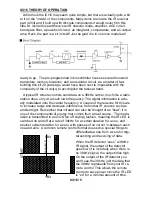
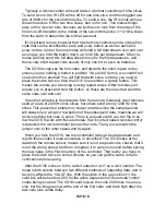
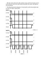
A typical IR remote controls send data on a 38kHz carrier, much like a radio 

station does, only at a much lower frequency. The digital information is actu-
ally modulated onto the carrier frequency. A couple of the reasons for this are 
to increase range and decrease interference from other IR sources such as 
ambient light. Remember that infrared can also be thought of as “heat”; it is 
one of the components of energy that comes from a heat source.  The modu-
lation is transmitted in an OOK (on off keying) fashion, meaning the IR LED is 
switched on and off at a rate of 38kHz for a certain duration for a one, and 
another certain duration for a zero, with pauses of no carrier in-between each 
one and zero. A common remote control format does some special things to 

differentiate a one from a zero for digi-
tal sending and receiving of data. 

When the IR detector “sees” a 38kHz 
IR signal, the output of the detector 
goes low (it is inverted), when there is 
no 38kHz signal, the output idles high. 
On the output of the IR detector you 
won’t see the 38kHz, just the data that 
the 38kHz represents from your IR re-
mote control. This allows the remote 
control to save power since the IR LED 
is “on” for a minimal amount of time. 

SA

MP

LE 

0 Bit 

1 Bit 

ST

AR

T


Summary of Contents for ICI16

Page 1: ...te control up to 11 meters away Outputs a 4 bit number for each button pushed giving you 16 possible codes Up to 16 buttons can be used Receives IR from a remote control or an RF signal from our wireless IR remote repeater the RRW1A 5VDC regulated operation Convenient LED indicator lets you know infrared and programming status Mode jumper for various interfaces to microcontrollers or external ICs ...

Page 2: ... RAMSEY AMATEUR RADIO KITS HR Series HF All Mode Receivers QRP Series HF CW Transmitters CW7 CW Keyer DDF1 Doppler Direction Finder QRP Power Amplifiers RAMSEY MINI KITS Many other kits are available for hobby school Scouts and just plain FUN New kits are always under development Write or call for our free Ramsey catalog ICI16 REMOTE INTERFACE KIT MANUAL Ramsey Electronics publication No ICI16 Rev...

Page 3: ...E OF CONTENTS Introduction 4 Theory of Operation 5 Learn As You Build 8 Parts List 10 Parts Placement Diagram 11 Assembly Steps 12 Testing and Programming 14 Example Hookups 16 Troubleshooting 17 Specifications 19 Schematic Diagram 22 Warranty 23 KIT ASSEMBLY AND INSTRUCTION MANUAL FOR ...

Page 4: ...is typically a large molded sheet of rubber with the buttons protruding outward The end of the button that you cannot see is typically coated with a carbon dot that will make contact with the printed circuit board underneath completing the circuit when the button is depressed no it s not sad it is just making contact This switch closure will cause an Integrated Circuit on the circuit board to repe...

Page 5: ...y The digital information is actu ally modulated onto the carrier frequency A couple of the reasons for this are to increase range and decrease interference from other IR sources such as ambient light Remember that infrared can also be thought of as heat it is one of the components of energy that comes from a heat source The modu lation is transmitted in an OOK on off keying fashion meaning the IR...

Page 6: ...these are the ones that send the same code over and over One other variance is the data rate from the remote Generally most remotes send at a rate of 2400 Hz time slices but others send at only 1200 Hz time slices This presents a problem on slower remotes since the sample period will always lie in a high or low portion of the subsequent data meaning we will receive nothing but ones or zeros There ...

Page 7: ...e 200 valid codes will yield 200 low pulses Normally the line is held high The following shows the progress of receiving five valid codes programmed for code 4 in mode 1 and mode 0 DATA0 DATA1 DATA2 DATA3 VALID DATA0 DATA1 DATA2 DATA3 VALID CODE1 CODE2 CODE3 CODE4 CODE5 MODE0 MODE1 0 1 0 0 0 1 0 0 0100b 4 ...

Page 8: ...our soldering iron tip gently heat the traces to which you are soldering heating both wires and pads simultaneously Apply the solder on the iron and the pad when the pad is hot enough to melt the solder The finished joint should look like a drop of water on paper somewhat soaked in We ll mount most of the electrical parts on the top side of the board provided When installing parts the component sh...

Page 9: ... avoid the urge to jump ahead installing components Since you may appreciate some warm up soldering practice as well as a chance to put some landmarks on the PC board we ll first install some of the larger components This will also help us to get acquainted with the up down left right orientation of the circuit board Have a look at the parts layout diagram to help with your assembly Use the boxes ...

Page 10: ... R3 8 10K ohms brown black orange R9 R10 R11 R12 R13 R19 R20 R21 1 100K ohms brown black yellow R4 2 1M ohm resistor brown black green R2 R7 1 22M ohm resistor red red blue R5 1 100K ohm potentiometer R1 Inductors 2 33nH coil Inductors L1 L2 Semiconductors and Integrated Circuits 1 MICRF001BN receiver data demodulator U1 1 68HC908JK1 Pre programmed microcontroller U2 1 IR Sensor Module U3 1 LED D1...

Page 11: ...ICI16 11 ICI16 PARTS LAYOUT DIAGRAM ...

Page 12: ...marked on the board drawing and PC board silkscreen 6 Install R3 470 ohm resistor yellow violet brown to the left of Q1 Install it vertical style 7 Install C1 0 01 uF ceramic disc capacitor marked 103 above C1 8 Install R4 100K ohm resistor brown black yellow up and to the right of C1 9 Install L2 33 nH inductor air coil to the right of R4 10 Install C8 0 1 uF ceramic disc capacitor marked 104 abo...

Page 13: ... marked 103 above H1 27 Install R12 10K ohm resistor brown black orange above C12 28 Install R13 10K ohm resistor brown black orange next to R12 29 Install R21 10K ohm resistor brown black orange Next to R13 30 Install the IC socket for U2 above C10 Then insert the 68HC908JK1 microcontroller Line up the notch on the chip with the notch on the board drawing Be sure all the IC pins are in the socket...

Page 14: ...ock The switches should face the outside of the PC board to make it easier to flip them later 48 We have one last part to install and it s going on the back side of the board with the first connectors we installed It is the IR sensor module U3 It goes into the three holes next to C14 Check its position on the topside of the board then install it on the bottom Leave the leads standing up off the bo...

Page 15: ... shorter pulse trains or you may see the pulse train being repeated over and over If you have access to an oscilloscope you can even observe this pulse train on the detector output pin which is tied to pins 1 and 19 of the microcontroller Now we will set our controller to the learn mode to memorize the pulse trains from our remote and configure the switch S2 to learn 16 codes as we move along The ...

Page 16: ... seen Mode 1 would be used in this case To latch and hold a relay in position use a Flip Flop 74HC74 as shown for relay 2 and 5 Code 14 turns on relay 5 and turns off relay 2 and code 15 turns on relay 2 and turns off relay 5 The relays will stay in those states until you send a code 14 or 15 to change their states again To interface to a microcontroller for a variety of tasks connect as shown whe...

Page 17: ...h S8 see chart on page 15 5 The jumper on H1 is set to RF rather than IR Try swapping positions 6 It is an ancient remote that has a hammer and chimes inside Those just won t work this is for IR remotes or our RRW1A remote RF repeater 7 You are trying to yse an IR remote that is modulated at some other fre quency than 38kHz There are some other ranges available but 38kHz is by far the most common ...

Page 18: ...ave another set of eyes look through your work Here at the shop we have often run into a stone wall of a problem only to have a fellow technician see our obvious error It is sometimes very difficult to see your own mistake taking a break can often solve this common problem Make sure that you have checked all the assembly steps boxes you may have forgotten one or two of them PROBLEM I just can t ma...

Page 19: ...njoy the use of this Ramsey product As always we have tried to compose our manual in the easiest most user friendly format that is possible As our customers we value your opinions comments and additions that you would like to see in future publications Please submit comments or ideas to Ramsey Electronics Inc Attn Hobby Kit Department 590 Fishers Station Drive Victor NY 14564 Please also feel free...

Page 20: ...ICI16 20 These pages were intentionally left blank to provide plenty of room for notes ...

Page 21: ...ICI16 21 ...

Page 22: ...ICI16 22 ...

Page 23: ...ch be assured that the 1K ohm resistors are actually the missing 10 K parts Hum m m I guess the red band really does look orange Ramsey Electronics project kits are packed with pride in the USA If you believe we packed an incorrect part or omitted a part clearly indicated in your assembly manual as supplied with the basic kit by Ramsey please write or call us with information on the part you need ...

Page 24: ...ication No MICI1 Assembly and Instruction manual for RAMSEY MODEL NO ICI16 REQUIRED TOOLS Soldering Iron Ramsey RTS06 Thin Rosin Core Solder Ramsey RTS12 Needle Nose Pliers Ramsey RTS05 Small Diagonal Cutters Ramsey RTS04 ADDITIONAL SUGGESTED ITEMS Soldering Iron Holder Cleaner RS64 2078 Holder for PC Board Parts Ramsey RTS13 Desoldering Braid Ramsey RTS08 ESTIMATED ASSEMBLY TIME Beginner 2 hrs In...

Reviews: