20
Example 4.1
Toshiba T series – Modbus Master:
This configuration can be used to make Toshiba PLC function as a Modbus Master. Configure Gateway ports
as: PLC1 Protocol: Toshiba T Series PLC and PLC2 Protocol: Modbus (Master). PLC1 of Gateway is
configured as Toshiba T series master protocol so T series PLCs can be connected to PLC1 of Gateway.
PLC2 port is configured as Modbus master so any Modbus slave device can be connected on PLC2.
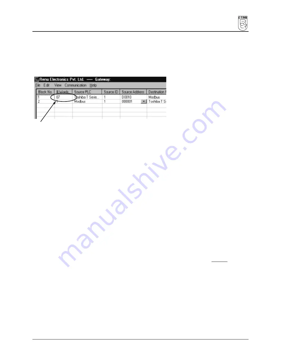
Blocks can be defined as shown in the picture below:
# Words defines number of registers/coils to be read / written between two devices.
Block #1: Gateway reads 7 words starting from D0010 from Toshiba T1 PLC and write these seven words
data to Modbus slave device in holding registers starting from 400001.
Block #2: Gateway reads Modbus output coil 000001 and writes it to Toshiba output coil Y002/3.
As this example has only two blocks, Gateway will execute Block #1 after executing Block #2 continuing
this cycle forever.
Notes:
1)
Maximum 255 blocks can be configured in any mode.
2)
Multiple bits read / write is not supported except for Toshiba PLC. For other PLC’s single
bit can read / write at a time.
3)
In Master-Master configuration, typical time required to execute one block is 75 msec.
approx.
4.1.2
Master-Slave configuration
In this mode, one of the Gateway ports is a master and other is the slave so the devices connected on these
ports are slave and master respectively. Blocks do not control data transfer in this mode. Data transfer takes
place only when Master Device, connected on slave port of Gateway, sends a request to read / write data.
This mode requires mapping registers / coils for data transfer. Mapping means defining one or multiple
registers / coils in the Slave Device corresponding to one or multiple registers / coils in the Master Device.
Mapping can be done using the Block definition area, so in this mode, any Block is used for mapping
registers / coils of the two devices.
In Block Definition area, # Words Field indicates number of registers / coils to be mapped linearly from the
starting addresses of the Source Device to the Destination Device. Maximum number of registers / coils that
can be mapped is 255, but this does not mean that Master Device has to read / write 255 registers / coils in
one command. For example, if user wants to map register DM0 to DM9, he has to define a single block of 10
registers starting from DM0.
In one command Master can read / write registers / coils from one Block only, so if multiple registers
are to be read / written using a single command, # Words also limits the maximum number of registers /
coils to be read / written. Number of registers to be read /written in one command also depends on
- protocol of BOTH the devices
- Buffer capacity of Gateway.
Please refer to Example 4.2 for description on defining register / coil maps in Master - Slave configuration.
Summary of Contents for GWY-00
Page 1: ...GATEWAY USER S MANUAL ...
Page 25: ...25 TYPICAL PROJECTS In this chapter Project Setup Example 1 Example 2 Example 3 ...
Page 30: ...30 CONFIGURATION SOFTWARE In this chapter System Requirements Installation Instructions ...
Page 32: ...32 CABLE DIAGRAMS In this chapter Wiring Diagrams Communication Cable ...
Page 34: ...34 COMMUNICATION CABLES FOR GWY 00 ...
Page 69: ...69 COMMUNICATION CABLES FOR GWY S7 ...
Page 83: ...83 COMMUNICATION CABLES FOR GWY S8 ...
Page 85: ...85 IBM CABLES ...
Page 88: ...88 TROUBLESHOOTING GUIDE ...
Page 104: ...CIV INDEX ...


