RTD Embedded Technologies, Inc.
| www.rtd.com
36
DM35418HR/DM35218HR
User’s Manual
BDM-610010041 Rev F
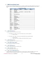
6.1.7
GBC_USER_ID
(R
EAD
O
NLY
)
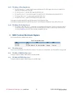
This value is set by jumpers on the board, and is used to identify individual board when there are multiple in the same system.
6.1.8
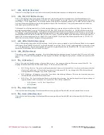
GBC_IRQ_STATUS
(R
EAD
/C
LEAR
)
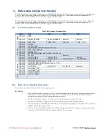
This is a 64-bit interrupt status register for non-DMA interrupts. Each bit in this register corresponds to one of the Function Blocks; bit 0
corresponds to FB0 (whose ID and OFFSET are at 0x020), etc. Bits 60 through 63 are reserved. This is a “sticky” register, and the driver clears
it by writing a ‘1’ to the appropriate bit. The interrupts signaled by this registered are generally handled by a User Mode Delayed Procedure Call.
Any status information required to service the interrupt must be latched in the Function Block. This typically means that there will also be a
sticky status register in the Function Block.
The Interrupt Service Routing must be able to clear the interrupt without accessing any registers in the Function Block. This means that if a
persistent interrupt condition occurs (i.e. FIFO Empty) the GBC_IRQ_STATUS register will initially be set. The ISR will then clear the bit in
GBC_IRQ_STATUS and launch the DPC. In this state the interrupt condition still exists, but the status bit is cleared (because we are servicing
it). Depending on implementation, that Function Block may not be able to issue another interrupt while in this state. In this state the full status of
the board cannot be determined just from the GBC_IRQ_STATUS register. The Function Block should also maintain a status register that will
indicate if the interrupt condition still exists, which will be cleared by the DPC. By doing an End-Of-Interrupt (see Section 6.1.10 GBC_EOI
(Read/Clear) below) any “hidden” interrupts will be generated again.
6.1.9
GBC_DIRQ_STATUS
(R
EAD
/C
LEAR
)
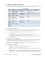
This is a 64-bit interrupt status register for DMA interrupts. Each bit in this register corresponds to one of the Function Blocks; bit 0 corresponds
to FB0 (whose ID and OFFSET are at 0x020), etc. Bits 60 through 63 are reserved. This is a “sticky” register, and the driver clears it by writing
a ‘1’ to the appropriate bit. The interrupts signaled by this registered are generally handled by the Kernel Mode ISR. This interrupt is only for
the Function Block Standard DMA in Section 6.2 on page 37.
6.1.10
GBC_EOI
(R
EAD
/C
LEAR
)
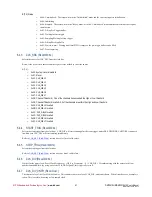
This register is used to acknowledge an interrupt. It is used to safeguard against missing an interrupt. At the end of the ISR, write a 0x01 to this
register. If there is another interrupt pending in the status registers, the interrupt line is toggled (Legacy Mode), or another interrupt is sent (MSI
Mode).
6.1.11
FB
N
_ID
(R
EAD
-O
NLY
)
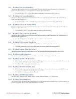
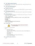
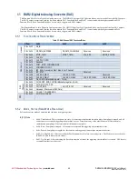
This is a 32-bit value that identifies the type of Function Block in slot ‘n’. Any changes to a Function Block result in a new Block ID. The
mappings for the Functional Block ID can be found on page 34. The ID consists of three fields:
B[31:24] Type Revision – This is used to indicate the addition of features to the function block. Any checks in the software should be
of the form (Type Revision > NN) so that the driver doesn’t fail with a newer FPGA. Any changes to the FPGA that would break
existing software must change the Type, not the Type Revision.
B[23:16] Subtype – A Subtype is a variant of the Type with one of the following differences. This allows the driver and library to use
the same functions, but have different enumerations.
B[15:0] Type – The Type of the Function Block is used to define the register map. Any time that the positions of registers change, or
registers are added or removed require a new Type number. This is loosely separated into
o
B[15:8] Family – i.e. ADC, DAC, Digital I/O, etc.
o
B[7:0] Member
6.1.12
FB
N
_O
FFSET
(R
EAD
-O
NLY
)
This is the offset from the beginning of the Functional Block section (typically the offset in BAR2) that this Functional Block resides in.
6.1.13
FB
N
_O
FFSET
_DMA
(R
EAD
-O
NLY
)
This is the offset from the beginning of the Functional Block section (typically the offset in BAR2) that the Functional Block DMA Registers
resides in.

