SHARP PC-G850V(S) User Manual -
Appendix A: 11-Pin Interface
18
The following image shows the pin-out of a PIC16F84A as a representative:
The PIC-loader of the PC-G850V(S) supports the ICSP-protocol as stated above, but
preceding to that there is a connection test phase. If it fails, the programming process
stops and the message
Connection error!
is shown on the display.
In order to get into more details of the PIC-loader dynamics, we take a minimalistic
example code for the PIC16F84A. It just consists of the configuration word and an infinite
loop without body:
10 #include ”p16f84a.inc”
20 __config 0x3ff6
30loop goto loop
The PIC-assembler compiles this source code into a PIC machine language program
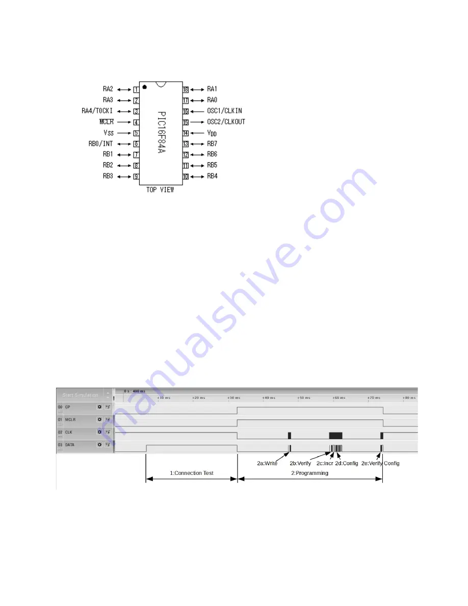
with only one PIC-word (14-bit). The next diagram shows the phases of a successful
burning process controlled by the integrated PIC-loader of the PC-G850V(S):
CLK was strobed at the RB6-input of the PIC (i.e. the already inverted CLK# signal). DATA was stobed at
the RB7-pin. CP directly controls the programming voltage at the MCLR#-pin.


