Configuration
4.11 Communication with the CPU
CP 1243-8 IRC
98
Operating Instructions, 02/2018, C79000-G8976-C385-03
PLC tag for partner status / path status
The two statuses are stored in a common PLC tag of Word or UInt type (DB, bit memory,
output).
The two statuses occupy one byte of the PLC tag. The coding is written separately for byte 0
(partner status) and byte 1 (path status).
Partner status
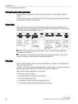
Byte 0 of the common PLC tag for partner status / path status codes information on the
availability of the communications partner, on the existing connections and connection paths
and on the status of the send buffer of the CP.
Bit 7
Bit 6
Bit 5
Bit 4
Bit 3
Bit 2
Bit 1
Bit 0
Path redun-
dancy
Connection
mode
Temporary
connection
**
(Re-
served)
Frame memory * Path status
Partner
status
0: No re-
dundancy
1: Redun-
dancy exists
0: Perma-
nent
1: Tempo-
rary
0: Partner
not reacha-
ble
1: Partner
reachable *
-
0: Send buffer OK
1: Memory alloca-
tion > 90 %
3: overflow
(memory alloca-
tion 100 %)
0: Not all
paths
reachable
1: All paths
reachable
0: Partner
not reacha-
ble
1: Partner
reachable
* Partners that support temporary connections are set to 'reachable' if the partner itself
terminates the connection.
** For the behavior of the frame memory, refer to the section "Send buffer" in the section
Process image, type of transmission, event classes (Page 144).
Path status
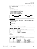
Byte 1 shows the status of the connection path (configured connection) to the partner from
the point of view of the CP.
A maximum of 2 paths (main and substitute path) to a partner can be configured, see section
Creating telecontrol connections for the ST7 communication (Page 122).
Both connection paths must start or end at the CP.
The PLC tag shows the following:
●
The paths via which the partner can be reached.
●
The path currently being used
●
The interface via which the main path was configured.
●
The interface via which the substitute path was configured.

