Modbus RS485 Stepper Drive User Manual
17
Message:
01
06
18 01
22 11
06 06
Description
Address
Function code Register address
Write data
CRC check code
Slave>master data:
Message:
01
06
18 01
22 11
06 06
Description
Address
Function code
Register address
Write data
CRC check code
Note: 0x1801-- Auxiliary control word, and 0x2211 is to save the value to EEPROM. This step is required after the
parameter has been modified, to prevent losing the written value after power-off.
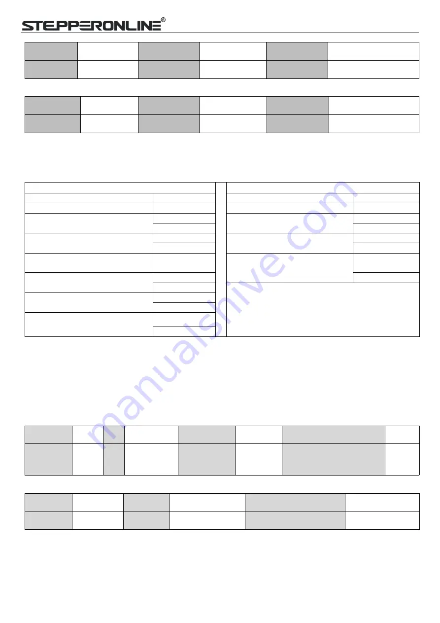
4.2.3 Preset Multiple Registers FC= 10
Preset Multiple Registers Query (Master to Slave)
Preset Multiple Registers Response (Slave to Master)
Slave ID
00 - 1F
Slaver ID
00 - 1F
FC
10
FC
10
Address of first register to write to
High
Address of first register written to
High
Low
Low
Total number of registers to write
to
High
Total number of registers written
to
High
Low
Low
Number of data bytes in message
2 bytes per
register
CRC
Low
Value1 to write
High
High
Low
-
Value2 to write
High
Low
CRC
Low
High
Example E: Write multiple registers-- configure input port functions
Send message:01 10 01 46 00 04 08 00 00 00 28 00 00 00 29 1C 14
Receive message:01 10 01 46 00 04 21 E3
Details as following:
Master->slave data:
Message
01
10
01 46
00 04
08
00 00, 00 28, 00 00, 00 29
1C 14
Description Slave
ID
FC First address
write
Number of
address write
Number of
bytes
Value to write
CRC
Slave>master data:
Message
01
10
01 46
00 04
21 E3
Description Slave ID
FC
First address write
Number of address write
CRC
Note: (1) In above example, modify the function of DI2 / DI3, and write the value as DI2=0x28 ( means path 0),
DI2=0x29 (means path 1);
(2) The data type of parameter is 32bit, which include high 16bit register and low 16bit register.usually , we use low


