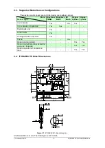
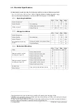
background image


iPOS4808 VX 


Intelligent Servo Drive for 

Step, DC, Brushless DC and 

AC Motors


Intelligent Servo Drive


Technical  

Reference 


 Technosoft 2018 


Summary of Contents for iPOS4808 VX

Page 1: ...iPOS4808 VX Intelligent Servo Drive for Step DC Brushless DC and AC Motors Intelligent Servo Drive Technical Reference Technosoft 2018 ...

Page 2: ...X Technical Reference P091 027 iPOS4808 VX UM 0818 Technosoft S A Avenue des Alpes 20 CH 2000 NEUCHATEL Switzerland Tel 41 0 32 732 5500 Fax 41 0 32 732 5504 e mail contact technosoftmotion com http www technosoftmotion com ...

Page 3: ...n programming using one of the options A CANopen master1 The drive s built in motion controller executing a Technosoft Motion Language TML program developed using Technosoft EasyMotion Studio software A TML_LIB motion library for PCs Windows or Linux A TML_LIB motion library for PLCs A distributed control approach which combines the above options like for example a host calling motion functions pr...

Page 4: ...EasySetUp part fully functional can be downloaded free of charge from Technosoft web page TML_LIB v2 0 part no P091 040 v20 UM xxxx explains how to program in C C C Visual Basic or Delphi Pascal a motion application for the Technosoft intelligent drives using TML_LIB v2 0 motion control library for PCs The TML_lib includes ready to run examples that can be executed on Windows or Linux x86 and x64 ...

Page 5: ... general information or assistance see Note Ask questions about product operation or report suspected problems see Note Make suggestions about or report errors in documentation see Note World Wide Web http www technosoftmotion com Email contact technosoftmotion com Fax 41 32 732 55 04 Email hotline technosoftmotion com Mail Technosoft SA Avenue des Alpes 20 CH 2000 Neuchatel Switzerland ...

Page 6: ... BR B 9 Digital Inputs IN0 IN1 IN2 LSP IN3 LSN IN4 Enable IN5 IN6 IN7 9 Digital Outputs OUT0 OUT1 OUT2 Error OUT3 Ready OUT5 10 Digital Hall Inputs Hall1 Hall2 Hall3 10 Encoder Inputs A A A B B B Z Z Z 11 Linear Hall Inputs LH1 LH2 LH3 11 Sin Cos Encoder Inputs Sin Sin Cos Cos 12 Analog 0 5V Inputs REF FDBK 12 Axis ID Inputs AxisID 0 AxisID 1 Axis ID 2 12 RS 232 12 CAN Bus 13 Supply Output 5V 13 i...

Page 7: ...301 Application Layer and Communication Profile Overview 53 CiA 402 and Manufacturer Specific Device Profile Overview 54 TechnoCAN Extension 54 Checking Setup Data Consistency 54 5 2 Using the built in Motion Controller and TML 54 Technosoft Motion Language Overview 54 Installing EasyMotion Studio 55 Getting Started with EasyMotion Studio 55 Creating an Image File with the Setup Data and the TML P...

Page 8: ... Brushless motor with sine cosine encoder on motor 71 6 4 Jerk units 71 Brushless DC brushed motor with quadrature encoder on motor 71 Brushless motor with linear Hall signals 72 DC brushed motor with quadrature encoder on load and tacho on motor 72 Step motor open loop control No feedback device 72 Step motor open loop control Incremental encoder on load 73 Step motor closed loop control Incremen...

Page 9: ...DC brushed motor with tacho on motor 78 Step motor open loop control No feedback device or incremental encoder on load 78 Step motor closed loop control Incremental encoder on motor 79 Brushless motor with sine cosine encoder on motor 79 7 Memory Map 80 ...

Page 10: ...IONS TO PREVENT THIS SITUATION CAUTION SIGNALS A DANGER FOR THE DRIVE WHICH MIGHT DAMAGE THE PRODUCT OR OTHER EQUIPMENT MAY INCLUDE INSTRUCTIONS TO AVOID THIS SITUATION CAUTION INDICATES AREAS SENSITIVE TO ELECTROSTATIC DIS CHARGES ESD WHICH REQUIRE HANDLING IN AN ESD PROTECTED ENVIRONMENT 1 1 Warnings WARNING TO AVOID ELECTRIC ARCING AND HAZARDS NEVER PLUG UNPLUG THE iPOS4808 FROM IT S SOCKET WHI...

Page 11: ...ations regarding Article 33 of the European REACH Regulation 1907 2006 Registration Evaluation Authorization and Restriction of Chemicals which came into force on 01 06 2007 RoHS Compliance Technosoft SA here with declares that this product is manufactured in compliance with the RoHS directive 2002 95 EC on the restriction of the use of certain hazardous substances in electrical and electronic equ...

Page 12: ...operations Performing data transfers between axes Controlling motion of an axis from another one via motion commands sent between axes Sending commands to a group of axes multicast This includes the possibility to start simultaneously motion sequences on all the axes from the group Synchronizing all the axes from a network By implementing motion sequences directly at drive level you can really dis...

Page 13: ...es all the TML instructions With EasyMotion Studio you can fully benefit from a key advantage of Technosoft drives their capability to execute complex motions without requiring an external motion controller thanks to their built in motion controllers EasyMotion Studio shall be used to program motion sequences in TML This is the iPOS4808 typical operation mode when TMLCAN protocol is selected EasyM...

Page 14: ...ce up to 115200 bps CAN bus 2 0B up to 1Mbit s with hardware axis ID selection1 Two operation modes CANopen conforming with CiA 301 v4 2 and CiA DSP 402 v3 0 TMLCAN intelligent drive conforming with Technosoft protocol for exchanging TML commands via CAN bus 2K 16 internal SRAM memory for data acquisition 4K 16 E2ROM to store TML programs and data PWM switching frequency up to 100kHz Motor supply ...

Page 15: ... Yes Yes Digital halls only Yes Linear Halls Yes Analogue Sin Cos encoder Yes Tacho Yes Open loop no sensor Yes Yes Open loop with step loss detection using incr Encoder Yes Yes Open loop with incr encoder on load Yes Yes 2 4 iPOS4808 VX Drive Dimensions 39 15 12 15 41 5 14 5 0 5 0 5 B49 B1 56 0 0 1 36 8 0 0 1 4 4 9 0 5 23 4 2 4 1 9 0 1 0 7 2 2 6 2 5 9 5 3 5 3 4 4 2 4 0 1 3 0 1 6 9 0 2 1 6 0 15 0 ...

Page 16: ...Mechanical Mounting Min Typ Max Units Airflow natural convection3 closed box Spacing required for vertical mounting see Figure 3 2 Between adjacent drives 30 mm Between drives and nearby walls 30 mm Between drives and roof top 20 mm Spacing required for horizontal mounting see Figure 3 5 Between adjacent drives 4 mm Between drives and nearby walls 5 mm Space needed for drive removal 10 mm Between ...

Page 17: ...rotection degree According to IEC60529 UL508 IP00 Logic Supply Input VLOG Min Typ Max Units Supply voltage Nominal values 9 36 VDC Absolute maximum values drive operating but outside guaranteed parameters 8 40 VDC Absolute maximum values continuous 0 6 42 VDC Absolute maximum values surge duration 10ms 1 45 V Supply current VLOG 7V 125 320 mA VLOG 12V 85 220 VLOG 24V 50 145 VLOG 40V 40 120 Motor S...

Page 18: ... 60 kHz 120 FPWM 80 kHz 80 FPWM 100 kHz 60 Absolute minimum value limited by short circuit protection VMOT 48 V FPWM 20 kHz 120 µH FPWM 40 kHz 40 FPWM 60 kHz 30 FPWM 80 kHz 15 FPWM 100 kHz 8 Motor electrical time constant L R Recommended value for 5 current measurement error due to ripple FPWM 20 kHz 250 µs FPWM 40 kHz 125 FPWM 60 kHz 100 FPWM 80 kHz 63 FPWM 100 kHz 50 Current measurement accuracy...

Page 19: ...OG VLOG Absolute maximum continuous 0 5 VLOG 0 5 Absolute maximum surge duration 1s 1 VLOG 1 Output current Logic LOW sink current continuous 0 5 A Logic LOW sink current pulse 5 sec 1 A Logic HIGH source current external load to GND VOUT 2 0V OUT2 Error OUT3 Ready 2 mA OUT0 OUT1 4 mA Logic HIGH leakage current external load to VLOG VOUT VLOG max 40V 0 1 0 2 mA Minimum pulse width TBD µS ESD prote...

Page 20: ...uency Single ended mode Open collector NPN 0 500 kHz Input frequency Differential mode or Single ended driven by push pull TTL CMOS 0 10 MHz Minimum pulse width Single ended mode Open collector NPN 1 µS Differential mode or Single ended driven by push pull TTL CMOS 50 nS Input voltage any pin to GND Absolute maximum values continuous 7 7 V Absolute maximum surge duration 1s 11 14 ESD protection Hu...

Page 21: ...ation 1s 36 Input impedance To GND 7 kΩ Resolution 12 bits Integral linearity 2 bits Offset error 2 10 bits Gain error 1 3 FS2 Bandwidth 3dB Depending on software settings 0 0 8 kHz ESD protection Human body model 5 kV Axis ID Inputs AxisID 0 AxisID 1 Axis ID 2 Min Typ Max Units External connections 7 levels Not connected Strap to GND Strap to 5V 4 7kΩ to GND 4 7kΩ to 5V 22kΩ to GND 22kΩ to 5V Pin...

Page 22: ... 2 1 127 CANopen 1 195 255 TMLCAN Voltage CAN Hi or CAN Lo to GND 26 26 V ESD protection Human body model 15 kV Supply Output 5V Min Typ Max Units 5V output voltage Current sourced 250mA 4 8 5 5 2 V 5V output current 600 650 mA Short circuit protection NOT protected Over voltage protection NOT protected ESD protection Human body model 1 kV Stresses beyond values listed under absolute maximum ratin...

Page 23: ...gure 2 3 iPOS4808 VX CAN De rating with ambient temperature Figure 2 4 iPOS4808 VX CAN De rating with altitude Figure 2 5 iPOS4808 VX CAN Over current diagram CAUTION FOR PWM FREQUENCIES LESS THAN 20 KHZ CORRELATE THE PWM FREQUENCY WITH THE MOTOR PARAMETERS IN ORDER TO AVOID POSSIBLE MOTOR DAMAGE 1 VOUT the output voltage VMOT the motor supply voltage ...

Page 24: ... by natural convection The motherboard can be mounted horizontally or vertically In both cases the air temperature must not exceed the limits indicated Figure 3 2 shows the recommended spacing to assure proper airflow by natural convection in the worst case closed box done from a plastic non metallic material with no ventilation openings Whenever possible ventilation openings shall be foreseen on ...

Page 25: ...perature surrounding the iPOS4808 drive s inside the limits indicated then alternate forced cooling methods must be applied For thermal calculations each iPOS4808 drive can be assumed to generate 1 5 Watt 5 BTU hour at idle and up to TBD Watt worst case while driving a motor Horizontal Mounting When iPOS4808 is mounted horizontally its overall envelope size including the recommended mating connect...

Page 26: ...orst case closed box done from a plastic non metallic material with no ventilation openings Whenever possible ventilation openings shall be foreseen Recommendations for their size and position are presented in par 3 1 2 Remark In case of using a metallic box with ventilation openings all spacing values may be reduced substantially With proper ventilation keep the air surrounding the iPOS4808 insid...

Page 27: ...r to fulfill the basic requirement of zero common mode current through the filter This is necessary because the ground negative return is shared between VMOT and VLOG Motor outputs shall be routed with parallel traces and minimizing the loop area between these tracks Avoid placing components above or below the motor output tracks as these components may become effective antennas radiating EMI If p...

Page 28: ...gainst ESD and over voltage add high frequency filtering to protect against external noise injected on 5VOUT The outer box case cabinet must be connected to the motherboard ground either galvanically directly or through high frequency decoupling capacitors rated at an appropriate voltage CAUTION WHEN iPOS4808 IS SET IN TMLCAN MODE IT STARTS TO EXECUTE AUTOMATICALLY AT POWER ON THE TML APPLICATION ...

Page 29: ... card edge connector 1 0mm pitch 2x49 contacts Tyco 3 1775801 4 Samtec PCIE 098 02 F D TH PCIe 8x horizontal card edge connector 1 0 mm pitch 2x49 contacts Tyco 1761465 3 Samtec PCIE 098 02 F D RA 3 4 Connector and Connection Diagrams Connector Layout J1 A12 A1 A11 A49 J1 B11 B49 B12 B1 J1 Top view Figure 3 7 iPOS4808 VX drive connector J1 ...

Page 30: ...l Reference Identification Labels J1 J1 P027 01x E001 LABEL LABEL SERIAL NUMBER Identification label with Technosoft serial number Identification label with Technosoft part number A side B side Figure 3 8 iPOS4808 VX CAN Identification Labels ...

Page 31: ... CAN Bus and RS 232 pins B4 OUT0 O 5 36V 0 5A general purpose digital output NPN open collector TTL pull up B5 AxisID 0 I Axis ID Address input 7 states floating strap to GND or 5V resistor 4K7 or 22K to GND or 5V B6 AxisID 1 I Axis ID Address input 7 states floating strap to GND or 5V resistor 4K7 or 22K to GND or 5V B7 AxisID 2 I Axis ID Address input 7 states floating strap to GND or 5V resisto...

Page 32: ...re L3 L4 L5 L6 Figure 3 9 shows how to set the 7 levels on the AxisID 0 input and the resulting axis ID values when AxisID 2 input level is set for CANopen operation Table 3 1 shows how to set all possible values for axis ID in this mode of operation Remarks 1 AxisID value is computed with formula 49 x AxisID2 7 x AxisID1 AxisID0 where each AxisID can have one of the integer values 0 to 6 0 for L0...

Page 33: ... Technosoft 2018 25 iPOS4808 VX Technical Reference Figure 3 9 Axis ID Setting Examples CANopen mode ...

Page 34: ... Technosoft 2018 26 iPOS4808 VX Technical Reference Figure 3 10 Axis ID Setting Examples TMLCAN mode ...

Page 35: ... L0 L3 L2 23 L0 L3 L3 24 L0 L3 L4 25 L0 L3 L5 26 L0 L3 L6 27 L0 L4 L0 28 L0 L4 L1 29 L0 L4 L2 30 L0 L4 L3 31 L0 L4 L4 32 L0 L4 L5 33 L0 L4 L6 34 L0 L5 L0 35 Axis ID 2 Axis ID 1 Axis ID 0 ID CANopen L0 L5 L1 36 L0 L5 L2 37 L0 L5 L3 38 L0 L5 L4 39 L0 L5 L5 40 L0 L5 L6 41 L0 L6 L0 42 L0 L6 L1 43 L0 L6 L2 44 L0 L6 L3 45 L0 L6 L4 46 L0 L6 L5 47 L0 L6 L6 48 L1 L0 L0 49 L1 L0 L1 50 L1 L0 L2 51 L1 L0 L3 5...

Page 36: ...00 L2 L0 L3 101 L2 L0 L4 102 L2 L0 L5 103 L2 L0 L6 104 L2 L1 L0 105 L2 L1 L1 106 L2 L1 L2 107 L2 L1 L3 108 L2 L1 L4 109 Axis ID 2 Axis ID 1 Axis ID 0 ID CANopen L2 L1 L5 110 L2 L1 L6 111 L2 L2 L0 112 L2 L2 L1 113 L2 L2 L2 114 L2 L2 L3 115 L2 L2 L4 116 L2 L2 L5 117 L2 L2 L6 118 L2 L3 L0 119 L2 L3 L1 120 L2 L3 L2 121 L2 L3 L3 122 L2 L3 L4 123 L2 L3 L5 124 L2 L3 L6 125 L2 L4 L0 126 L2 L4 L1 255 L2 L4...

Page 37: ...L3 L3 L4 25 L3 L3 L5 26 L3 L3 L6 27 L3 L4 L0 28 L3 L4 L1 29 L3 L4 L2 30 L3 L4 L3 31 L3 L4 L4 32 L3 L4 L5 33 L3 L4 L6 34 L3 L5 L0 35 L3 L5 L1 36 Axis ID 2 Axis ID 1 Axis ID 0 ID TMLCAN L3 L5 L2 37 L3 L5 L3 38 L3 L5 L4 39 L3 L5 L5 40 L3 L5 L6 41 L3 L6 L0 42 L3 L6 L1 43 L3 L6 L2 44 L3 L6 L3 45 L3 L6 L4 46 L3 L6 L5 47 L3 L6 L6 48 L4 L0 L0 49 L4 L0 L1 50 L4 L0 L2 51 L4 L0 L3 52 L4 L0 L4 53 L4 L0 L5 54 ...

Page 38: ...104 L5 L1 L0 105 L5 L1 L1 106 L5 L1 L2 107 L5 L1 L3 108 L5 L1 L4 109 L5 L1 L5 110 L5 L1 L6 111 L5 L2 L0 112 L5 L2 L1 113 Axis ID 2 Axis ID 1 Axis ID 0 ID TMLCAN L5 L2 L2 114 L5 L2 L3 115 L5 L2 L4 116 L5 L2 L5 117 L5 L2 L6 118 L5 L3 L0 119 L5 L3 L1 120 L5 L3 L2 121 L5 L3 L3 122 L5 L3 L4 123 L5 L3 L5 124 L5 L3 L6 125 L5 L4 L0 126 L5 L4 L1 127 L5 L4 L2 128 L5 L4 L3 129 L5 L4 L4 130 L5 L4 L5 131 L5 L4...

Page 39: ...164 L6 L2 L4 165 L6 L2 L5 166 L6 L2 L6 167 L6 L3 L0 168 L6 L3 L1 169 L6 L3 L2 170 L6 L3 L3 171 L6 L3 L4 172 L6 L3 L5 173 L6 L3 L6 174 Axis ID 2 Axis ID 1 Axis ID 0 ID TMLCAN L6 L4 L0 175 L6 L4 L1 176 L6 L4 L2 177 L6 L4 L3 178 L6 L4 L4 179 L6 L4 L5 180 L6 L4 L6 181 L6 L5 L0 182 L6 L5 L1 183 L6 L5 L2 184 L6 L5 L3 185 L6 L5 L4 186 L6 L5 L5 187 L6 L5 L6 188 L6 L6 L0 189 L6 L6 L1 190 L6 L6 L2 191 L6 L6...

Page 40: ... supply VLOG for using the 24V outputs 2 The maximum sink current is 0 5A continuous up to 1A pulsed for less than 5 seconds 3 The inputs are compatible with NPN type outputs input must be pulled to GND to change it s default state 4 The outputs are compatible with NPN type inputs load is tied to common VLOG output pulls to GND when active and is floating when inactive ...

Page 41: ...onnection Figure 3 12 5V Digital I O connection Remarks 1 The inputs are compatible with TTL 5V LVTTL 3 3V CMOS and open collector outputs 2 The outputs are compatible with TTL 5V inputs 3 The output loads can be individually and independently connected to 5V or to GND ...

Page 42: ...is differential and the signal source ground is isolated from the drive GND use a 2 wire twisted shielded cable as follows 1st wire connects the source plus positive in phase to the drive analogue input 2nd wire connects the source minus negative out of phase to the drive ground GND Shield is connected only at the drive side to the drive GND and is left unconnected at the source side c If the anal...

Page 43: ... Motor connections 3 4 9 1 Brushless Motor connection Figure 3 15 Brushless motor connection 3 4 9 2 2 phase Step Motor connection Figure 3 16 2 phase step motor connection one coil per phase Figure 3 17 2 phase step motor connection two coils per phase ...

Page 44: ...ble for the motor wires Connect the cable shield to the iPOS4808 GND pin Leave the other end disconnected b The parasitic capacitance between the motor wires must not bypass 10nF If very long cables tens of meters are used this condition may not be met In this case add series inductors between the iPOS4808 outputs and the cable The inductors must be magnetically shielded toroidal for example and m...

Page 45: ...ended Incremental Encoder Connection Figure 3 20 Single ended incremental encoder connection 3 4 10 2 Differential Incremental Encoder Connection Figure 3 21 Differential incremental encoder connection Remark 120Ω 0 25W terminators are required for long encoder cables or noisy environments ...

Page 46: ... Technosoft 2018 38 iPOS4808 VX Technical Reference 3 4 10 3 Digital Hall Connection Figure 3 22 Digital Hall connection 3 4 10 4 Linear Hall Connection Figure 3 23 Linear Hall connection ...

Page 47: ... another twisted pair for the 5V supply and GND b Always use shielded cables to avoid capacitive coupled noise when using single ended encoders or Hall sensors with cable lengths over 1 meter Connect the cable shield to the GND at only one end This point could be either the iPOS4808 using the GND pin or the encoder motor Do not connect the shield at both ends c If the iPOS4808 5V supply output is ...

Page 48: ... during braking During abrupt motion brakes or reversals the regenerative energy is injected into the motor power supply This may cause an increase of the motor supply voltage depending on the power supply characteristics If the voltage bypasses 53V the drive over voltage protection is triggered and the drive power stage is disabled In order to avoid this situation you have 2 options Option 1 Add ...

Page 49: ...n can be found in the Drive Setup dialogue within EasyMotion EasySetup The braking will occur when DC bus voltage increases over UBRAKE This parameter UBRAKE should be adjusted depending on the nominal motor supply Optimally from a braking point of view UBRAKE should be a few volts above the maximum nominal supply voltage This setting will activate the brake resistor earlier before reaching danger...

Page 50: ...ON Serial RS 232 connection 3 4 12 1 Serial RS 232 connection Figure 3 26 Serial RS 232 connection 3 4 12 2 Recommendation for wiring a If you build the serial cable you can use a 3 wire shielded cable with shield connected to BOTH ends Do not use the shield as GND The ground wire pin B3 of J1 must be included inside the shield like the 232Rx and 232Tx signals b Always power off all the iPOS4808 s...

Page 51: ...e must be 105 135 ohms 120 ohms typical and a capacitance below 30pF meter b When using a printed circuit board PCB motherboard based on FR 4 material build the CAN network using a pair of 12mil 0 012 tracks spaced 8 to 10mils 0 008 0 010 apart placed over a local ground plane microstrip which extends at least 1mm left and right to the tracks c Whenever possible use daisy chain links between the C...

Page 52: ...n from address 0x4000 b Hardware by temporary connecting all digital Hall inputs to GND during the power on for about 1s until the green led is turned on as shown in Figure 3 29 This option is particularly useful when it is not possible to communicate with the drive After the drive is set in non Autorun slave mode using 2nd method the 1st method may be used to invalidate the TML application from t...

Page 53: ...AN interface or using Technosoft Ethernet to CAN adapter 3 Via another drive from the same CAN bus network connected to the PC via one of the above options from point 1 The output of EasySetUp is a set of setup data which can be downloaded into the drive EEPROM or saved on your PC for later use EasySetUp includes a set of evaluation tools like the Data Logger the Control Panel and the Command Inte...

Page 54: ... Help button of the dialogue opened Here you can find detailed information about how to setup your drive and do the connections Power on the drive then close the Communication Setup dialogue with OK If the communication is established EasySetUp displays in the status bar the bottom line the text Online plus the axis ID of your drive motor and its firmware version Otherwise the text displayed is Of...

Page 55: ... the motor technology for example brushless or brushed and type of feedback device for example Incremental encoder Linear Halls The selection opens 2 setup dialogues for Motor Setup and for Drive setup through which you can configure and parameterize a Technosoft drive plus several predefined control panels customized for the product selected ...

Page 56: ... setup Download setup data to drive motor Press the Download to Drive Motor button to download your setup data in the drive motor EEPROM memory in the setup table From now on at each power on the setup data is copied into the drive motor RAM memory which is used during runtime It is also possible to Save the setup data on your PC and use it in other applications To summarize you can define or chan...

Page 57: ...verted into 255 and the drive is set with CAN communication non configured mode waiting for a CANopen master to configure it using CiA 305 protocol A non configured drive answers only to CiA 305 commands All other CANopen commands are ignored and transmission of all other CANopen messages including boot up is disabled In absence of a CANopen master you can get out a drive from non configured mode ...

Page 58: ...CAN 1 to 127 for CANopen or can indicate that axis ID will be set according with the AxisID inputs levels d If the setup table is invalid there is no previous axis ID set from a valid setup table or by a CANopen master according with the AxisID inputs levels Remark If you don t know the axis ID set in a drive you can find it in the following way a Connect the drive via a serial RS232 link to a PC ...

Page 59: ...ue see above with the value read from the setup table This value can be one of the above 4 values or the firmware default F W default which is 500kbs b If a valid setup table exists and this setup table was created with the Set baud rate checkbox unchecked in the Drive Setup dialogue see above with the last value set either from a valid setup table or by a CANopen master via CiA 305 protocol c If ...

Page 60: ...irst data to write at start address second data to write at start address 1 etc All the data are hexadecimal 16 bit values maximum 4 hexadecimal digits Each raw contains a single data value When less then 4 hexadecimal digits are shown the value must be right justified For example 92 represent 0x0092 The sw file can be programmed into a drive from a CANopen master using the communication objects f...

Page 61: ...vices which are performed with no protocol overhead Transmit PDOs are used to send data from the drive and receive PDOs are used to receive on to the drive The iPOS4808 accepts 4 transmit PDOs and 4 receive PDOs The contents of the PDOs can be set according with the application needs using the dynamic PDO mapping This operation can be done during the drive configuration phase using SDOs Synchroniz...

Page 62: ...d connection set as defined by CiA 301 Thus TechnoCAN protocol and CANopen protocol can co exist and communicate simultaneously on the same physical CAN bus without disturbing each other Checking Setup Data Consistency During the configuration phase a CANopen master can quickly verify using the checksum objects and a reference sw file see 0 and 5 2 4 for details whether the non volatile EEPROM mem...

Page 63: ... the demo version and then purchase a license By introducing the license serial number in the menu command Help Enter registration info you can transform the demo version into a fully functional version Getting Started with EasyMotion Studio Using EasyMotion Studio you can quickly do the setup and the motion programming of a Technosoft a drive according with your application needs The drive can be...

Page 64: ...ng runtime The motion component contains the motion sequences to do These are described via a TML Technosoft Motion Language program which is executed by the drives motors built in motion controller 5 2 3 1 Create a new project EasyMotion Studio starts with an empty window from where you can create a new project or open a previously created one When you start a new project EasyMotion Studio automa...

Page 65: ...or brushed and the type of feedback device for example incremental encoder Click on your selection EasyMotion Studio opens the Project window where on the left side you can see the structure of a project At beginning both the new project and its first application are named Untitled The application has 2 components S Setup and M Motion program ...

Page 66: ...cation Setup dialogue press the Help button and check troubleshoots Remark When first started EasyMotion Studio tries to communicate via RS 232 and COM1 with a drive having axis ID 255 default communication settings If the drive has a different axis ID and you don t know it select in the Communication Setup dialogue at Axis ID of drive motor connected to PC the option Autodetected If this drive is...

Page 67: ...your PC and use it in other applications Note that you can upload the complete setup data from a drive motor To summarize you can define or change the setup data of an application in the following ways create a new setup data by going through the motor and drive dialogues use setup data previously saved in the PC upload setup data from a drive motor EEPROM memory 5 2 3 4 Program motion In the proj...

Page 68: ...ds from your host master using one of the communication channels and protocols supported by the drives use menu command Application Binary Code Viewer Using this tool you can get the exact contents of the messages to send and of those expected to be received as answers 5 2 3 5 Evaluate motion application performances EasyMotion Studio includes a set of evaluation tools like the Data Logger the Con...

Page 69: ...n electronic camming is used the cam tables can be loaded in the following ways a The master downloads the cam points into the drive active RAM memory after each power on b The cam points are stored in the drive EEPROM and the master commands their copy into the active RAM memory c The cam points are stored in the drive EEPROM and during the drive initialization transition to Ready to Switch ON st...

Page 70: ...ligent drives It is an ideal tool for quick implementation on PCs of motion control applications with Technosoft products With the TML Motion Library functions you can communicate with a drive motor via any of its supported channels RS 232 CAN bus etc send motion commands get automatically or on request information about drive motor status check and modify its setup parameters read inputs and set ...

Page 71: ...s and variables represented in the drive internal units IU These correspond to various signal types position speed current voltage etc Each type of signal has its own internal representation in IU and a specific scaling factor This chapter presents the drive internal units and their relation with the international standard units SI In order to easily identify them each internal unit has been named...

Page 72: ...ines _ encoder _ No rad Position _ Load π 4 2 where No_encoder_lines is the encoder number of lines per revolution Step motor open loop control No feedback device The internal position units are motor µsteps The correspondence with the load position in SI units is IU Position _ Motor Tr steps _ No steps _ No SI Position _ Load µ π 2 where No_steps is the number of motor steps per revolution No_µst...

Page 73: ... interpolated encoder counts The correspondence with the load position in SI units is For rotary motors IU Position _ Motor Tr ion Interpolat periods _ Enc SI Position _ Load π 4 2 For linear motors IU Position _ Motor Tr ion Interpolat accuracy _ Encoder SI Position _ Load where Enc_periods is the rotary encoder number of sine cosine periods or lines per revolution Interpolation is the interpolat...

Page 74: ... _ Motor T Tr resolution SI Speed _ Load π 2 For linear motors Pole_Pitch Load_Speed SI Motor_Speed IU resolution Tr T where resolution is the motor position resolution Tr transmission ratio between the motor displacement in SI units and load displacement in SI units T is the slow loop sampling period expressed in s You can read this value in the Advanced dialogue which can be opened from the Driv...

Page 75: ... No SI Speed _ Load µ π 2 where No_steps is the number of motor steps per revolution No_µsteps is the number of microsteps per step You can read change this value in the Drive Setup dialogue from EasySetUp Tr transmission ratio between the motor displacement in SI units and load displacement in SI units T is the slow loop sampling period expressed in s You can read this value in the Advanced dialo...

Page 76: ...otors IU Speed _ Motor T Tr ion Interpolat periods _ Enc SI Speed _ Load π 4 2 For linear motors IU Speed _ Motor T Tr ion Interpolat accuracy _ Encoder SI Speed _ Load where Enc_periods is the rotary encoder number of sine cosine periods or lines per revolution Encoder_accuracy is the linear encoder accuracy in m for one sine cosine period Interpolation is the interpolation level inside an encode...

Page 77: ...orrespondence with the load acceleration in SI units1 is For rotary motors IU on Accelerati _ Motor T Tr resolution SI on Accelerati _ Load π 2 2 For linear motors 2 Pole_Pitch Load_Acceleration SI Motor_Acceleration IU resolution Tr T where resolution is the motor position resolution Tr transmission ratio between the motor displacement in SI units and load displacement in SI units T is the slow l...

Page 78: ...Drive Setup dialogue from EasySetUp Tr transmission ratio between the motor displacement in SI units and load displacement in SI units T is the slow loop sampling period expressed in s You can read this value in the Advanced dialogue which can be opened from the Drive Setup Step motor open loop control Incremental encoder on load The internal acceleration units are load encoder counts slow loop sa...

Page 79: ...U on Accelerati _ Motor T Tr ion Interpolat periods _ Enc SI on Accelerati _ Load π 2 4 2 For linear motors IU on Accelerati _ Motor T Tr ion Interpolat accuracy _ Encoder SI on Accelerati _ Load 2 where Enc_periods is the rotary encoder number of sine cosine periods or lines per revolution Encoder_accuracy is the linear encoder accuracy in m for one sine cosine period Interpolation is the interpo...

Page 80: ...ion SI Jerk _ Load π 3 2 For linear motors 3 Pole_Pitch Load_Jerk SI Motor_Jerk IU resolution Tr T where resolution is the motor position resolution Tr transmission ratio between the motor displacement in SI units and load displacement in SI units T is the slow loop sampling period expressed in s You can read this value in the Advanced dialogue which can be opened from the Drive Setup Pole_Pitch i...

Page 81: ...y The correspondence with the load jerk in SI units is IU Jerk _ Load T lines _ encoder _ No SI Jerk _ Load π 3 4 2 where No_encoder_lines is the rotary encoder number of lines per revolution T is the slow loop sampling period expressed in s You can read this value in the Advanced dialogue which can be opened from the Drive Setup Step motor closed loop control Incremental encoder on motor The inte...

Page 82: ...rent units refer to the motor phase currents The correspondence with the motor currents in A is IU Current Ipeak A Current 65520 2 where Ipeak is the drive peak current expressed in A You can read this value in the Drive Info dialogue which can be opened from the Drive Setup 6 6 Voltage command units The internal voltage command units refer to the voltages applied on the motor The significance of ...

Page 83: ...internal time units are expressed in slow loop sampling periods The correspondence with the time in s is IU Time T s Time where T is the slow loop sampling period expressed in s You can read this value in the Advanced dialogue which can be opened from the Drive Setup For example if T 1ms one second 1000 IU 6 9 Master position units When the master position is sent via a communication channel the m...

Page 84: ...ole_Pitch is the magnetic pole pitch NN distance expressed in m DC brushed motor with quadrature encoder on load and tacho on motor The motor position is not computed Step motor open loop control No feedback device The internal motor position units are motor µsteps The correspondence with the motor position in SI units1 is IU Position _ Motor steps _ No steps _ No SI Position _ Motor µ π 2 where N...

Page 85: ...curacy is the linear encoder accuracy in m for one sine cosine period 6 12 Motor speed units Brushless DC brushed motor with quadrature encoder on motor The internal motor speed units are encoder counts slow loop sampling period The correspondence with the motor speed in SI units is For rotary motors IU Speed _ Motor T lines _ encoder _ No SI Speed _ Motor π 4 2 where No_encoder_lines is the rotar...

Page 86: ... expressed in V You can read this value in the Drive Info dialogue which can be opened from the Drive Setup Tacho_gain is the tachometer gain expressed in V rad s DC brushed motor with tacho on motor The internal motor speed units are A D converter bits The correspondence with the motor speed in SI units is IU Speed _ Motor gain _ Tacho Range _ Input _ ue log Ana SI Speed _ Motor 4096 where Analog...

Page 87: ...ed in s You can read this value in the Advanced dialogue which can be opened from the Drive Setup Brushless motor with sine cosine encoder on motor The internal motor speed units are interpolated encoder counts slow loop sampling period The correspondence with the motor speed in SI units is For rotary motors IU Speed _ Motor T ion Interpolat periods _ Enc SI Speed _ Motor π 4 2 For linear motors I...

Page 88: ...e The E2ROM is mapped in the address range 4000h to 4FFFh It is used to keep in a non volatile memory the TML programs the cam tables and the drive setup information Remark EasyMotion Studio handles automatically the memory allocation for each motion application The memory map can be accessed and modified from the main folder of each application Figure 7 1 iPOS4808 VX Memory Map TML Programs 4000h...

Reviews: