


Chapter 3
SNVU166 – FEBRUARY 2013
GUI Configuration and Description
3.1
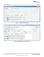
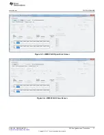
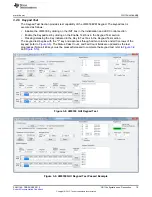
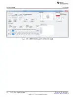
GUI Installation
1. Extract the zip file to a temporary folder.
Figure 3-1. LM8330EVM GUI Installation Files
2. Open the setup.exe file and click Install to finish the GUI installation.
14
GUI Configuration and Description
SNVU166 – FEBRUARY 2013
Copyright © 2013, Texas Instruments Incorporated


