1
PROGRAMMING CODE SHEET
T
Tiig
ge
err 3
38
80
0 S
Se
erriie
es
s
Code blanking
Code blanking blanks out all function codes
not required by the application. This means
that specific procedures such as recalibra-
tion and setpoint reprogramming can be
achieved in a few simple steps from the
front panel buttons.
To turn code blanking and macro settings
OFF, carry out the Code Blanking and
Macro Check on Page 3.
Display text editing
This function allows displayed text, such
as setpoint titles, to be edited to suit your
applications.
For example, a setpoint could be edited
to read [TNK_LO] for tank level low, or
[BRKOF] for brake off.
Configuration data copying
This function allows the current meter
configuration settings to be copied and
saved for later referral or for restoration.
Programming Tips
1)
Use the
button to step through the codes of
the
Main
or
Setpoint
Programming Mode.
2)
To save a
Main
Programming Mode code set-
ting and return directly to the operational display,
press the
button and then the
and
buttons at the same time.
3)
To save a
Setpoint
Programming Mode setting
and return directly to the operational display,
press the
button and then the
and
buttons at the same time.
4)
When configuring the three-digit code and set-
point settings, pressing the
and buttons
at the same time increases the displayed
parameter in increments of 100 counts.
Front panel programming
This programming code sheet (PCS) is a quick
reference document that allows you to quickly
view the controller's programming codes.
When you become familiar with the controller
and the programming code structure, the PCS
can be used in place of the user manual.
Programming via PC
Meter configuration utility program
With a serial output module installed, the
meter can be fully configured through the
meter configuration utility program
. In
addition to all application function settings,
the configuration program also provides
access to added features such as:
•
Code blanking.
•
Display text editing.
•
Configuration data copying.
•
Downloading macros to the meter.
Tamper-proof settings
Tiger 380 Series controllers (except the
DI-802) have tamper-proof lockout
switches to prevent users’ configuration
settings from being inadvertently
changed.
Code blanking is also used (via the PC)
to blank out codes not used, making
them operator tamper-proof, but leaving
selected codes available for operator
adjustment.
Macros
Texmate has a growing library of macros to
suit a wide range of standard customer
applications. Macros can be installed in the
controller, via the Tiger Development
System (TDS) or configuration program,
and run automatically when the meter is
powered up.
Prog.
SP1
SP2
SP4
SP3
SP5
SP6
Press
1
To configure the controller's programming
codes from the front panel, the controller uses
the three right-hand side display digits. These
are known as the 1st, 2nd, and 3rd digits and
can be seen in the diagram below.
Prog.
SP1
SP2
SP4
SP3
SP5
SP6
OPERATIONAL DISPLAY
1st
Digit
2nd
Digit
3rd
Digit
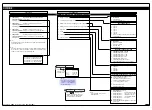
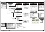
The logic diagram on Page 4 shows the code
structure of the Tiger 380 Series controller
range. The diagrams on the following pages
show the 3-digit settings available for each
code. The 3-digit default settings are
0
, indicat-
ed in bold text in each code.
Note:
All displays shown in this code
sheet are for a 6-digit, 14-seg-
ment alphanumeric display. Other
displays will be slightly different.
Contents
Initial Setup Procedures . . . . . . . . . . . . . . . . . . . . . . . . . . . . .2
Tiger 380 Series Code Logic Diagram . . . . . . . . . . . . . . . . .4
CALIBRATION MODE . . . . . . . . . . . . . . . . . . . . . . . . . . . . . .5
CODE 1 . . . . . . . . . . . . . . . . . . . . . . . . . . . . . . . . . . . . . . . . .8
CODE 2 . . . . . . . . . . . . . . . . . . . . . . . . . . . . . . . . . . . . . . . . .9
CODES 3 to 5 . . . . . . . . . . . . . . . . . . . . . . . . . . . . . . . . . . .10
CODES 6 to 9 . . . . . . . . . . . . . . . . . . . . . . . . . . . . . . . . . . .11
SETPOINT PROGRAMMING MODE – SPC_1 to SPC_6 .12
Detailed Descriptions and Explanations . . . . . . . . . . . . . . .15
Customer Code Settings – Main Programming Mode . . . . .16
Customer Code Settings – Setpoint Programming Mode . .19
Commonly Used Registers . . . . . . . . . . . . . . . . . . . . . . . . .20
Thermocouple Calibration for CH1 . . . . . . . . . . . . . . . . . . .21
RTD Calibration for CH1 . . . . . . . . . . . . . . . . . . . . . . . . . . .22
3
38
80
0
S
Se
erriie
es
s
Note:
3-digit programming codes are
specified within square brack-
ets [XXX].
If an X appears in the descrip-
tion of a 3-digit programming
code or in a configuration pro-
cedure, this means that more
than one choice can be made,
or any number displayed in
that digit is not relevant to the
function being explained.


