background image

60

How can I...

Perform resistance measurements

Some instruments have special hardware to perform resistance measurements. 

Setup resistance measurements

word SetupOhmMeasurements( word wMode )

Description:

This routine sets the instrument up to perform resistance measu-

rements. Several properties of the instrument are adapted: input

sensitivity,  signal  coupling,  record  length,  sampling  frequency,

auto  ranging,  trigger  source,  trigger  timeout,  acquisition  mode.

These are all brought to the required state and should not to be

set to other values afterwards.

Input:

wMode

0

switch resistance measurements off

1

switch resistance measurements on

Output:

Return value

E_NO_ERRORS

E_INVALID_VALUE

E_NOT_SUPPORTED

E_NO_HARDWARE

Retrieve the resistance values

After resistance measurements are switched on, and a measurement is perfor-

med  in  the  normal  way,  the  resistance  values  can  be  retrieved  by  using  the

function

word GetOhmValues( double *dValue1, double *dValue2 )

Description:

This routine retrieved the determined resistance values from the

instrument. This routine also performs averaging on the values,

only after 5 measurements the value is valid. 

The calling software is responsible for performing enough measu-

rements

Input:

-

Output:

dValue1

resistance value for Channel 1

dValue2

resistance value for Channel 2

Return value

E_NO_ERRORS

E_NOT_INITIALIZED

E_NOT_SUPPORTED

E_NO_HARDWARE

Summary of Contents for Handyscope HS3

Page 1: ...rammer s Manual TiePie DLLs for TP112 TiePieSCOPE HS508 TP208 TiePieSCOPE HS801 AWG TP508 Handyprobe HP2 TP801 AWG ISA Handyscope HS2 TP801 AWG PCI Handyscope HS3 TE6100 Handyscope HS4 DIFF Revision 1...

Page 2: ......

Page 3: ...r availability of DC hardware offset adjustment 15 Check for a square wave generator 15 Check for a function generator 15 Get the maximum amplitude of the function generator 16 Perform a measurement 1...

Page 4: ...sample clock status 32 Control the analog input channels 33 Get the current input sensitivity 33 Set the input sensitivity 33 Get the current auto ranging status 34 Set the auto ranging status 34 Get...

Page 5: ...ncy 51 Get the current generator frequency 51 Set the generator trigger source 52 Get the current generator trigger source 52 Fill the function generator waveform memory 53 Set the generator output st...

Page 6: ...6 Table of contents Retrieve the measured data in Volts 63 Get the current sampling frequency 63 Set the sampling frequency 63 Get the current trigger timeout value 63 Set the trigger timeout value 64...

Page 7: ...nstruments like e g the availability of a function generator or digital inputs and outputs When a certain function is called and the instrument does not support that functionality the routine will ret...

Page 8: ...8 Introduction...

Page 9: ...ROR 0x0040 0000000001000000 E_I2C_INVALID_ADDRESS 0x0080 0000000010000000 E_I2C_INVALID_SIZE 0x0100 0000000100000000 E_I2C_NO_ACKNOWLEDGE 0x0200 0000001000000000 Defined constants For several programm...

Page 10: ...10 How can I lCh1 1 lCh2 2 lCh3 3 lCh4 4 The routines that deal with the MeasureMode use different values mmCh1 1 mmCh2 2 mmCh3 4 mmCh4 8...

Page 11: ...tion constants in internal non volatile memory except for the TP208 and TP508 These have to be calibrated using internal routines This is done automatically at first startup everyday Some relays will...

Page 12: ...ing routine in C C day number 24 highest 8 bits month number 16 0xFF middle 8 bits year number 0xFFFF lowest 16 bits Input Output dwDate The calibration date Return value E_NO_ERRORS E_NOT_SUPPORTED E...

Page 13: ...easure input signals from 4 Volt 4 Volt input output dSensitivities the array of input sensitivities Return value E_NO_ERRORS E_NO_HARDWARE Determine the available input resolutions word GetAvailableR...

Page 14: ...maximum sampling fre quencies This routine queries the maximum sampling frequency Input Output Return value The maximum sampling frequency the instru ment supports in Hz Note The above function repla...

Page 15: ...n Some instruments have a built in square wave generator the HS508 for example This routine checks the presence of the generator Input Output Return value E_NO_ERRORS E_NO_GENERATOR E_NO_HARDWARE Chec...

Page 16: ...The maximum output voltage for the TiePieSCOPE HS801 and Handyscope HS3 generator is 12 Volt the maximum output voltage for the TP801 generator is 10 Volt This routine determi nes the maximum voltage...

Page 17: ..._INITIALIZED E_NO_ERRORS E_NO_HARDWARE Check if the hardware is measuring word ADC_Running void Description This routine checks if the hardware is currently measuring Input Output Return value 0 not m...

Page 18: ...1 Ch1 2 Ch2 Ch2 4 Ch3 External 8 Ch4 16 External Remark Return value can be a combination of indicated values Read the measurement status word ADC_Ready void Description This routine checks if the mea...

Page 19: ...h channel the data has to be retrieved Output wData The array to which the measured data of the requested channel should be passed Return value E_NO_ERRORS E_NO_HARDWARE Get the date from a specific c...

Page 20: ...there is enough space in the array to contain the data Therefore the size of the array in bytes must be at least RecordLength sizeof word Input Output Return value E_NO_ERRORS E_NOT_SUPPORTED E_NO_HA...

Page 21: ...hSensArray lCh1 8 0 SetSensitivity lCh1 ChSensArray lCh1 SetCoupling lCh1 lctAC Setup Ch2 20 Volt full scale range DC coupling ChSensArray lCh1 20 0 SetSensitivity lCh2 ChSensArray lCh2 SetCoupling lC...

Page 22: ...egin ADC_ForceTrig end if if ADC_Ready 1 then begin for wCh lCh1 to wChCount do begin ADC_GetDataChVolt wCh ChDoubleArray wCh end for ADC_Start StartTime GetCurrentTime ApplicationProcessData end if A...

Page 23: ...hich has to be set to this function using word SetDataReadyCallback TDataReady pAddress description This routines sets the pointer for the Ready function which will be called when new data is availabl...

Page 24: ...stored in the instrument When the measure ment is ready all data is transferred in one block to the computer This is normal oscilloscope mode ltmStream 1 Each time during the measure ment that new dat...

Page 25: ...reaming mode The record length has to be set to the number of samples that has to be measured each measurement There is no trigger and no pre or post trigger available in streaming mode A streaming me...

Page 26: ...esolution the new resolution in bits Output Return value E_NO_ERRORS E_INVALID_VALUE E_NOT_SUPPORTED E_NO_HARDWARE Remark When setting a new input resolution the maximum sampling frequency of the hard...

Page 27: ...K 2 operate as a 1 channel 12 bit instrument with 512K samples for the channel without generator Set the instrument configuration word SetIinstrumentConfig word wMode Description This routine changes...

Page 28: ...he signal at channel 2 is measured mmCh1 mmCh2 the signals at channel 1 and 2 are measu red simultaneously mmCh3 the signal at channel 3 is measured mmCh1 mmCh3 the signals at channel 1 and 3 are meas...

Page 29: ...lso the routines Get SetPostSamples Set the record length word SetRecordLength dword wTotal Description This routine sets the total number of points to be digitized The maximum record length can be de...

Page 30: ...the routines Get SetRecordLength Set the number of post samples word SetPostSamples dword wPost Description This routine sets the number of post samples This number must be between 0 and the record le...

Page 31: ...FrequencyF double dFreq Remarks The routine sets the sampling frequency The hardware is not capable of creating every selected frequency so the hardware chooses the nearest allowed frequency to use Th...

Page 32: ...status of the internal clock 0 clock internal 1 clock external Return value E_NO_ERRORS E_NOT_SUPPORTED E_NO_HARDWARE Set the sample clock status word SetExternalClock word wMode Description This rout...

Page 33: ...3 4 Output dSens The current sensitivity Return value E_NO_ERRORS E_INVALID_CHANNEL E_NO_HARDWARE Set the input sensitivity word SetSensitivity byte byCh double dSens Description This routine sets th...

Page 34: ...tivity The next measurement that is performed will be using that new sensitivity Auto ranging has no effect on a current measurement Input byCh The channel whose current Auto ranging mode is requested...

Page 35: ...byCh The channel whose current coupling is reque sted 1 2 3 4 Output byMode The current coupling Return value E_NO_ERRORS E_INVALID_CHANNEL E_INVALID_VALUE E_NO_HARDWARE Set the input coupling word S...

Page 36: ...E_NOT_SUPPORTED E_NO_HARDWARE Set the DC level value word SetDcLevel byte byCh double dLevel Description This routine is used to change the DC Level for the selected channel The DC Level has a minimum...

Page 37: ...S 10 not used ltsPxiExt 11 PXI bus digital trigger signals lts GenStart 12 start of the Handyscope HS3 generator ltsGenStop 13 stop of the Handyscope HS3 generator ltsGenNew 14 each new period of the...

Page 38: ...6 trigger on TV even frame sync pulse Input Output byMode The current trigger mode Return value E_NO_ERRORS E_INVALID_VALUE E_NO_HARDWARE Set the trigger mode word SetTriggerMode byte byMode Descripti...

Page 39: ...SUPPORTED E_NO_HARDWARE E_INVALID_CHANNEL Set the trigger mode for a specific channel word SetTriggerModeCh byte byCh byte byMode Description This routine is used to set the Trigger Mode for a specifi...

Page 40: ...rn value E_NO_ERRORS E_INVALID_CHANNEL E_NO_HARDWARE Set the trigger level word SetTriggerLevel byte byCh double dLevel Description This routine is used to set the Trigger Level The Trigger Level is v...

Page 41: ...lue E_NO_ERROR E_INVALID_CHANNEL E_NO_HARDWARE Set the trigger hysteresis word SetTriggerHys byte byCh double dHysteresis Description This routine changes the hysteresis see also GetTriggerHys Input b...

Page 42: ...h input state is active is determined by the Slopes setting see next page Input byEnables a bit pattern that defines which inputs have to be used Bit 0 represents input 0 bit 1 represents input 1 etc...

Page 43: ...low the corresponding input res ponds to a falling slope Output Return value E_NO_ERRORS E_NOT_SUPPORTED E_NO_HARDWARE Get the current PXI external trigger slopes word GetPXITriggerSlopes byte bySlop...

Page 44: ...outputs Input byValue the new status of the outputs Each bit repre sents an output Output Return value E_NO_ERRORS E_NOT_SUPPORTED E_NO_HARDWARE Get the current status of the digital outputs word Get...

Page 45: ...ene rator is available Set the square wave generator frequency word SetSquareWaveGenFrequency double dFreq Remarks The routine sets the frequency The hardware is not capable of using every frequency s...

Page 46: ...Mode dword dwMode Description The Handyscope HS3 function generator can be set to either linear mode or to DDS mode lfmDDS 1 DDS mode lfmLinear 2 Linear mode Input dwMode the requested function genera...

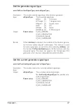
Page 47: ...of the function genera tor memory will be played continuously This memory is used for every signal type so each time when selecting Arbitrary use the function FillFuncGenMemory to fill the memory wit...

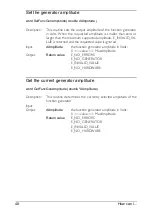
Page 48: ...sted value is ignored Input dAmplitude the function generator amplitude in Volts 0 value MaxAmplitude Output Return value E_NO_ERRORS E_NO_GENERATOR E_INVALID_VALUE E_NO_HARDWARE Get the current gener...

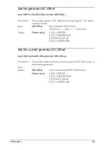
Page 49: ...n Volts MaxAmpl value MaxAmpl Output Return value E_NO_ERRORS E_NO_GENERATOR E_INVALID_VALUE E_NO_HARDWARE Get the current generator DC Offset word GetFuncGenDCOffset double dDCOffset Description This...

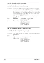
Page 50: ...kes 25 of the total period and the negati ve part takes 75 of the total period With signal types DC Noise and Arbitrary the symmetry value is ignored Input dSymmetry The requested symmetry value 0 val...

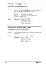
Page 51: ...62 78125 156250 312500 625000 1250000 2500000 5000000 10000000 25000000 50000000 The Handyscope HS3 AWG supports setting the sampling frequency at the same frequencies as the sampling frequency of the...

Page 52: ...tTrig 4 a digital external signal ltsNoTrig 9 no source generate immediately The default value is ltsNoTrig Input bySource the requested trigger source Output Return value E_NO_ERRORS E_INVALID_VALUE...

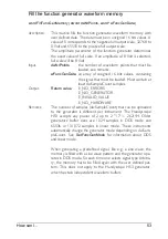
Page 53: ...ed Must contain at least dwSampleCount samples Output Return value E_NO_ERRORS E_NO_GENERATOR E_INVALID_VALUE E_NO_HARDWARE Remarks The number of samples dwSampleCount that can be uploaded to the gene...

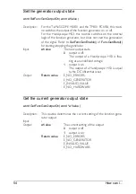
Page 54: ...the generator Input wValue The new output state 0 output is off The output of a Handyscope HS3 is floa ting at an undefined voltage 1 output is on The output of a Handyscope HS3 is equal to the DC of...

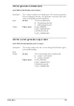
Page 55: ...te 0 Stop signal generation 1 Start signal generation Output Return value E_NO_ERRORS E_NO_GENERATOR E_INVALID_VALUE E_NO_HARDWARE Get the current generator output state word GetFuncGenOutputOn word w...

Page 56: ...finished the output will remain at the last ge nerated amplitude value Input wNrPeriods the requested number of periods to generate Any value 0 will switch on burst mode The value 0 will switch off b...

Page 57: ...e Get the I2 C bus speed word I2CGetSpeed dword dwSpeed Description The I2 C bus can operate on two frequencies 100 kHz and 400 kHz This routine will read the current bus speed Input Output dwSpeed Th...

Page 58: ...in bytes Output return value E_NO_ERRORS E_NO_HARDWARE E_NOT_SUPPORTED E_I2C_ERROR E_I2C_INVALID_ADDRESS E_I2C_INVALID_SIZE E_I2C_NO_ACKNOWLEDGE word I2CWriteNoStop dword dwAddress void pBuf dword dwS...

Page 59: ...in bytes Output return value E_NO_ERRORS E_NO_HARDWARE E_NOT_SUPPORTED E_I2C_ERROR E_I2C_INVALID_ADDRESS E_I2C_INVALID_SIZE E_I2C_NO_ACKNOWLEDGE word I2CReadNoStop dword dwAddress void pBuf dword dwS...

Page 60: ...ements off 1 switch resistance measurements on Output Return value E_NO_ERRORS E_INVALID_VALUE E_NOT_SUPPORTED E_NO_HARDWARE Retrieve the resistance values After resistance measurements are switched o...

Page 61: ...using these functions is deprecated Get the maximum sampling frequency dword GetMaxSampleFrequency void Continuing using this routine is deprecated use the routine GetMaxSampleFrequencyF instead Star...

Page 62: ...mentRaw word wCh1 word wCh2 Continuing using this routine is deprecated use the routine ADC_GetDataCh instead Get one sample of the measurement data binary word GetOneMeasurementRaw dword wIndex word...

Page 63: ...nt sampling frequency dword GetSampleFrequency void Continuing using this routine is deprecated use the routine GetSampleFrequencyF instead Set the sampling frequency word SetSampleFrequency dword dwF...

Page 64: ...ing using this routine is deprecated Note The Trigger Timeout applies only to measurements that are started with the obsolete routine StartMeasurement Measurements that are started using ADC_Start do...

Page 65: ...Deprecated routines 65...

Page 66: ...s and or remarks concerning the DLLs or the manual please contact TiePie engineering Koperslagersstraat 37 8601 WL SNEEK The Netherlands Tel 31 0 515 415 416 Fax 31 0 515 418 819 E_mail support tiepie...

Page 67: ...TiePie engineering DLL programmer s manual rev 1 26...

Reviews: