


Braking behaviour
Märklin Brake Distance
The decoder responds to a Märklin brake path (brakes with analog DC voltage on the track) when CV29 bit 2 and CV27 bit 4
or bit 5 are set to 1 (factory setting 1 and 0).
CV27 bit 4 = 1 -> DC with opposite direction of travel
CV27 bit 5 = 1 -> DC with direction of travel equal
ABC - Brakes
If the decoder detects an ABC braking distance (not possible safely when using an Intellibox, or Power 3 - 8), a braking
process begins. On which side of the rail the digital voltage should be more positive to activate the braking process can be set
via the CV27:
CV27 Bit0 = 1, brake when right rail is more positive
CV27 Bit1 = 1, brake when left rail is more positive
CV27 Bit0 & Bit1 = 1, brake regardless of which rail is more positive
Bit 7 of the CV27 can be used to set whether the vehicle should only react to the ABC braking distance in one direction of
travel (forward or backward). Only one of the bits 0 or 1 must be set for this. Regardless of the positions of bits 0 and 1 (one
must be at least set to detect an ABC braking distance) can be driven in an activated ABC braking distance when the shunting
gear is switched on or the starting braking deceleration is switched off. In the CV97, the voltage difference from which the
decoder detects the ABC braking distance can be set. The desired difference corresponds approximately to the CV value *
0.12V. If an ABC slow-moving signal is detected according to a Lenz BM2 module, the decoder brakes on the internal speed
step (0 - 255) adjustable in CV98.
Constant braking distance in cm
The decoder offers the possibility for two adjustable, constant braking distances in centimeters, true to scale.
The constant braking distances can be triggered by various events. This includes the ABC brake signal, the brake signal of a
DCC brake generator, the brake signal of a DC brake section, as well as the speed step 0 When braking with the speed step 0
(eg manual operation, LISSY or MARCo) it is possible to enter a speed step threshold, above which the constant braking
distance is only executed. If the internal speed of the locomotive decoder is smaller than the entered speed step threshold, the
vehicle stops at setpoint speed 0 with the set brake delay from CV4, or CV145, or CV147.
CV138 = 1 - 255 -> Instantaneous speed above which is braked with constant braking distance when the setpoint speed is set
to zero.
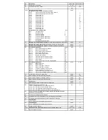
CV Meanings
CV139 = braking distance in cm
CV140 = alternative braking distance, can be activated via the CROSS bit (see "Extended Function Mapping")
CV141 = maximum speed of the model locomotive in cm/s
CV142 = If the value determined for the CV141 exceeds 255, the rest is entered in the CV142 (possibly track 1, IIm (G))
CV143 = constant braking distance activation by:
bit 0 = 1 -> setpoint speed = 0, with current internal speed according to CV138 and larger (manual operation, LISSY, MARCO)
bit 1 = 1 -> ABC brakes
Bit 2 = 1 -> DC Brakes
Bit 3 = 1 -> DCC brake signal
CV143 = 0 -> no constant braking distance
The meanings of CVs 141 and 142 described here are valid from software version 23 (CV7) of the decoder. For older software
versions, the 1st edition of this description remains valid.
If braking is initiated with a constant braking distance, the decoder only responds to driving commands again when the
locomotive has come to a standstill. This process can be interrupted by switching on the shunting gear.
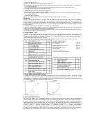
Determination of the maximum speed of the model locomotive
In the decoder, program the CV of the maximum speed to the maximum possible value (CV5 = 63, or when using the
extended speed characteristic CV94 = 255)
Mark a starting point on a sufficiently long, straight track section, from which the vehicle approx. 2 seconds unhindered can
drive at the maximum possible speed. Place a scale (ruler) at the marked starting point. Now you enter this section at
maximum speed, that is, throttle set to the highest speed. When you reach the starting point, start the time measurement for 2
seconds. After these 2 seconds, remember the position of the vehicle on the folding rule and read the value in cm. Divide this
value by 2 and you get the driven speed in cm/s. In the gauges 1 and IIm (G), the determined value may possibly exceed 255
for very fast vehicles. In this case, please enter the value 255 in the CV141 and the rest of the determined value in the
CV142.
After this measurement, the CV for the maximum speed (CV5 or CV94) can be set to the desired maximum speed for
driving operation.
Switchable starting and braking delays
In addition to the standard starting and braking deceleration (CVs 3 & 4) of the decoder, there are two alternative starting and
braking delays, which can be activated with function keys. The function keys F0 - F28 for the alternative ABV sets can be
stored by the values 0 - 28 in the respective CVs 148 and 149 (for simple function mapping, CV96 = 0). The value 255
disables the respective alternative ABV set.
CV144 = starting delay 2 as replacement for CV3
CV145 = brake delay 2 as replacement for CV4
CV146 = starting delay 3 as replacement for CV3
CV147 = Brake Deceleration 3 as replacement for CV4
CV148 = function key number for ABV 2 (0-12, 255=off)
CV149 = function key number for ABV 3 (0-12, 255=off)
In the extended function mapping (CV96 = 1), the alternative ABVs of the CVs 144 - 147 are activated via the possible
conditions there (see "Extended function mapping").
Function outputs
Simple function mapping
The following settings of the decoder are only possible with the simple function mapping (CV 96 = 0).
In the simple function mapping, the assignments of the switching tasks such as lighting, special function outputs (not 73115), shunting
and switchable starting and braking deceleration can be freely assigned to the function keys F0 to F12 of the digital control center. The
value that is written to a CV of the function mapping determines the functions that can be switched via a function key assigned to the CV.
For this purpose, the CVs 33 to 46 serve according to the following scheme.
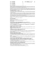
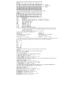
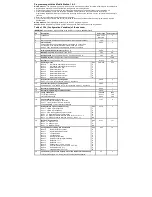
Assignment of the function keys to the CVs
Factory
value
Assignment of the individual bits
Wert
CV 33
Light function key F0 when driving forward
1
Bit 0
Front light output
1
CV 34
Light function key F0 when reversing
2
Bit 1
Rear light output
2
CV 35
Function key F1
4
Bit 2
Function output A1
4
CV 36
Function key F2
8
Bit 3
Function output A2
8
CV 37
Function key F3
16
Bit 4
Function output A3 (SUSI/logic)
16


