Page 10
WAMPLER METAVERSE
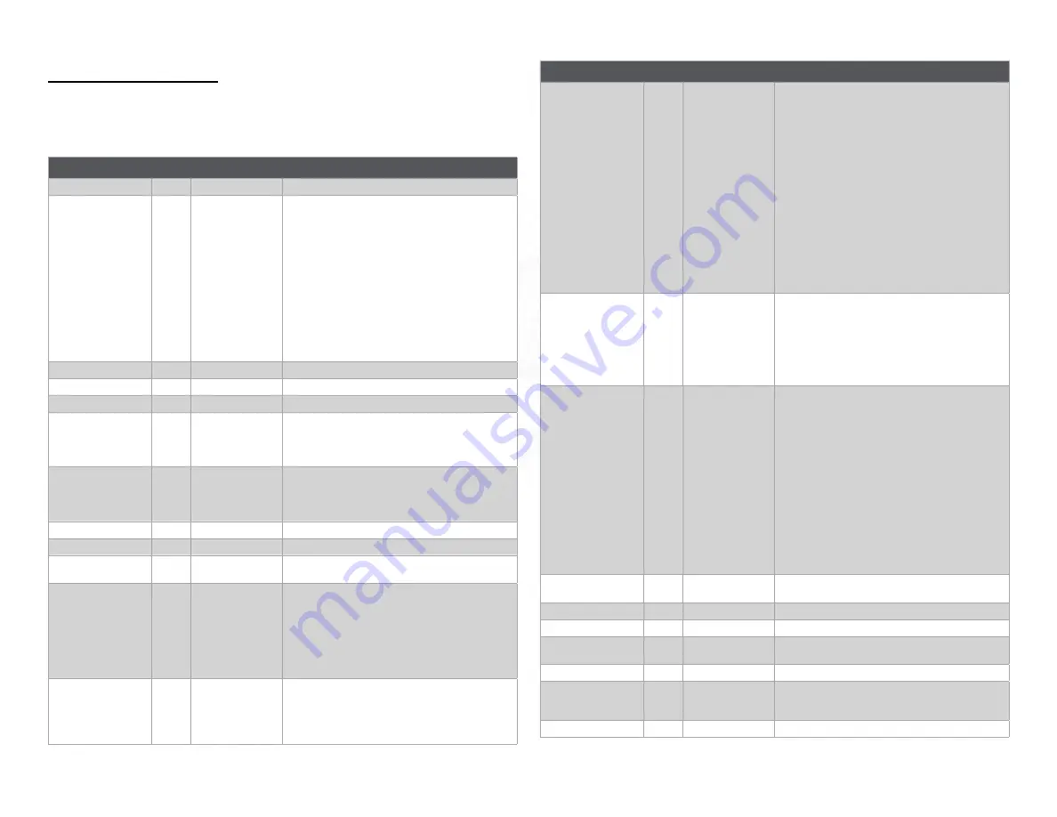
MIDI CC MESSAGES
Every Program can be controlled by sending CC Messages to
the device from a compatible MIDI controller as described in the
following table.
CC Function
CC no.
Value (0-127)
Description
Delay State
1
0=off, 1-127=on
Turns the delay on/off
Delay Program
2
0-10
Selects the delay program;
Send the corresponding MIDI CC value to select the
delay program:
0 - ANLG - Analog style delay
1 - WET - Modulated analog delay
2 - BBD - Bucket Brigade delay
3- JET - Analog flanger delay
4 - DOC - Wampler ‘The Doctor’
5 - FTE - Wampler ‘Faux Tape Echo’
6 - ETH - Wampler ‘Ethereal’ delay
7 - MOD - Digital flanger delay
8 - SPC - Space Echo delay
9 - TAPE - Multi head Tape delay
10 - DIGI - Digital delay
Delay Time (knob)
3
0-127
Emulates the Delay Time knob, 25ms to 2000ms
Delay Feedback (knob)
4
0-127
Emulates the Delay Feedback knob
Tone (knob)
5
0-127
Emulates the Tone knob
Mix (knob)
6
0-127
Emulates the Output Mix knob;
0 = dry 100% + wet 0%
95 = dry 100% + wet 100%
127 = dry 0% + wet 100%
Level (knob)
7
0-127
Emulates the Output Level knob;
0 = -6dB
63 = 0dB
127 = +6dB
Mod Depth (knob)
8
0-127
Emulates the Mod Depth knob
Mod Rate (knob)
9
0-127
Emulates the Mod Rate knob
Mod Feedback (knob)
10
0-127
Emulates the Mod Feedback knob - only affects JET
and MOD Programs
TAPE Mode
11
1-15
Selects head combination for TAPE Program ->
Value range selects heads in binary representation:
1000 (binary) = 8 (decimal) = head 1 (quarter)
0100 (binary) = 4 (decimal) = head 2 (dotted eighth)
0010 (binary) = 2 (decimal) = head 3 (eighth)
0001 (binary) = 1 (decimal) = head 4 (sixteenth)
See Note on Page 12 for full list of combinations
ETH Mode
12
0-3
Select the delay mode for the Ethereal Delay
0 = quarter
1 = q quarter triplet overlay
2 = q dotted eighth overlay
3 = q dotted eighth
CC Function
CC no.
Value (0-127)
Description
Subdivision
13
0-14
Sets the tap tempo subdivision ((0-7 are accessible via
the front panel) Select the Subdivision setting for the
Tap Tempo Switch and MIDI Clock
0 = Quarter
1 = Dotted Eighth
2 = Eighth
3 = Sixteenth
4 = Half
5 = Whole
6 = Dotted Quarter
7 = Triplet Quarter
8 = Dotted Sixteenth
9 = Dotted Half
10 = Dotted Whole
11 = Triplet Sixteenth
12 = Triplet Eighth
13 = Triplet Half
14 = Triplet Whole
Delay Time (high ms)
14
0-15
A Time High message followed by a Time Low message
will set the delay time to a specific ms value. It is possi-
ble to set very specific delay times (with 1ms resolution)
using two sequential MIDI commands.
First, send CC 14 with the high byte (calculated below)
Second, send CC 15 with the low byte (calculated
below)
Delay Time (low ms)
15
0-127
Each message is a 7-bit value, and sent together will
be interpreted as a 14-bit value. To set a specific delay
time in milliseconds using MIDI CC 14 and 15:
1. Determine high byte: take delay time in
milliseconds and divide by 128. The number left of
the decimal is the high byte. (eg. 400ms delay time ->
400/128 = 3.125 -> high byte = 3
2. Determine low byte: multiply the number right of
the decimal by 128. This is the low byte.
(eg. 400ms delay time -> 400/128 = 3.125 -> 0.125 ->
0.125 * 128 = 16 -> low byte = 16
3. Send MIDI CC 14 val=highbyte (3) first, and then
MIDI CC 15 val=lowbyte (16) second.
4. After receiving both bytes, the device will update
the delay time to match the received messages.
Tap Tempo
81
0
Emulates the tap tempo function of the tap tempo
switch
Preset Decrement
82
0-127
Decrements the Preset number by <value>
Preset Increment
83
0-127
Increments the Preset number by <value>
Tempo Switch Mode
84
0=tap tempo
1-127=Preset inc
Selects the mode of the tempo switch
Trails Mode
85
0=off, 1-127=on
Turns on/off trails mode
MIDI Clock Enable
99
0=off, 1-127=on
Enable or disable the MIDI Clock Sync:
0 = ignore MIDI Clock
1-127 = set tempo based on MIDI Clock
Expression Pedal
100
0-127
Emulates the expression pedal input
Summary of Contents for METAVERSE
Page 1: ...FULL USER GUIDE ...
Page 16: ......


